Do you have a question about the Norcold N500 and is the answer not in the manual?
Provides maintenance, diagnostic, and repair info for NORCOLD N500/N510 gas absorption refrigerators.
Identifies N500/N510 as 2-way and N500.3/N510.3 as 3-way refrigerators.
Location and details of the refrigerator's information label.
Describes the location of the cooling unit's serial number label.
Lists certifications and compliance standards for NORCOLD N500/N510 refrigerators.
States installation must conform to manual and applicable codes.
Emphasizes using only authorized NORCOLD replacement parts.
Provides contact information for NORCOLD Customer Service.
General safety precautions and recommended equipment for servicing.
Explains the meaning of WARNING and CAUTION safety alert symbols.
Lists critical safety warnings and precautions for operating and servicing the refrigerator.
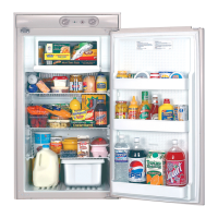
Details specifications for Norcold N500 gas/electric refrigerators.
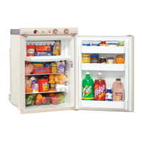
Details specifications for Norcold N510 gas/electric refrigerators.
Flowchart for diagnosing burner flame issues on N500 units.
Procedure to check the thermocouple and interrupter voltage output.
Flowchart for troubleshooting a blank display on N510 models.
Troubleshooting steps for N510 DC voltage high fault.
Troubleshooting steps for N510 DC voltage low fault.
Troubleshooting flowchart for N510 'A' fault code (no AC power).
Troubleshooting flowchart for N510 'S' fault code (flame sense failure).
Troubleshooting flowchart for N510 'H' fault code (AC heater failed open).
Troubleshooting flowchart for N510 'r' fault code (AC relay stuck closed).
Explains the Backup Operating System (BOS) functionality in N510 models.
Step-by-step guide to reset the N510 refrigerator's power board.
Covers roof exhaust, air intake vents, and baffles for proper airflow.
Details air intake and sidewall exhaust vents for slide-out installations.
Describes components like the orifice, manual shutoff valve, and safety valve.
Provides a step-by-step procedure for replacing the gas safety valve.
Details N510 components including solenoid gas valve and orifice.
Instructions for cleaning and maintaining the burner, flue tube, and flue baffle.
Guidelines for safely handling LP gas lines and fittings to prevent leaks.
Details methods like Method A, Method B, bubble tests, and pressure drop tests.
Covers AC power requirements, heater, and fuse for N500/N510 models.
Covers DC power requirements, DC heater, and relighter for N500/N510 models.
Specifies the fuse for the DC heater circuit.
Procedure for replacing AC or DC heaters.
Details AC power cord connections for N500 and N510 models.
Describes the N500 terminal block and its connections.
Explains using an AC/DC converter as a power source for N510.
Details the absorption system, heat transfer, and airflow dynamics.
Covers level operation, gradual efficiency loss, and cooling monitoring.
Identifies signs of refrigerant leakage and handling precautions.
Provides warnings and guidance on proper cooling unit disposal.
Steps to safely remove the refrigerator from its enclosure.
Detailed steps for removing the cooling unit from N500 and N510 models.
Steps for installing a replacement cooling unit, including N510 specifics.
Steps to reinstall the refrigerator into the enclosure and connect utilities.
Details the spark/sense electrode and its replacement.
Covers N500 relighter operation, flame indicator, and related replacements.
Procedure for replacing the selector switch on N500 models.
Details N510 power board removal and installation.
Procedure for replacing the N510 optical control circuit board.
Covers AUTO mode for all and 3-way units, including AC/LP operation.
Explains AUTO DC mode for 3-way units.
Describes AC Manual mode and its conditions.
Addresses issues related to no AC power or loss of AC power.
Covers LP Manual mode, flame ignition failure, and gas lock-out.
Details DC Manual mode for 3-way units.
Explains the diagnostic mode, its screens, and how to access it.
Instructions for changing and exiting diagnostic screens.
Details Screens 1, 2, and 3 for mode status, reliability, and temperature.
Details Screens 4 and 5 for accessing stored fault history data.
Procedure to erase stored fault history data from the diagnostic mode.
Describes Screens 7 and 8 for viewing power board inputs and outputs.
Details Screen 9 for checking the power board's DC voltage status.
Visual representation of N500 model wiring connections.
Visual representation of N510 model wiring connections.
| Brand | Norcold |
|---|---|
| Model | N500 |
| Category | Refrigerator |
| Language | English |