DRAFT
NOT FOR PUBLIC RELEASE
21
www.norcold.com/cda N500/N510 ModelsRefrigerator Service Manual
VENTILATION
Roof Exhaust Venting
Illustrations of different venting applications are shown
in Figure 13 and Figure 14.
Air Intake Vent
The ventilation and combustion air flows into the
enclosure through the air intake vent.
The space between the air intake vent and the rear of
the refrigerator must be kept clear at all times. Any
obstruction in this area may cause serious ventilation
problems. The air intake vent opening also provides
access for servicing cooling unit components.
Roof Exhaust Vent
The heat absorbed by ventilation air and combustion
gases flow out of the enclosure through the roof
exhaust vent.
The roof exhaust vent is equipped with a non-
removable metal mesh screen that prevents leaves,
debris, birds or rodents from getting into the enclosure.
The roof cap is fastened to the exhaust vent with four
screws. The cap is always installed with the slope
towards the front of the RV.
Baffles
The minimum and maximum clearances for installing
the refrigerator or correcting ventilation problems on
roof vented units are listed in Table 1. Baffles are
required whenever installations exceed maximum
clearances listed in Table 1. Figure 13 and Figure 14
show baffle locations.
NOTE
The general guidelines for intake vents and roof exhaust
vents presented in this section do not replace the
instructions and/or guidelines provided in the N500/
N510 Installation Manual and the Ventilation Guidelines
for Gas/Electric Refrigerators, part number 622090A (3-
01). Refer to the N500/N510 Installation Manual and
Ventilation Guidelines for Gas/Electric Refrigerators for
the latest information on approved vents, installation
instructions, and special construction exceptions.
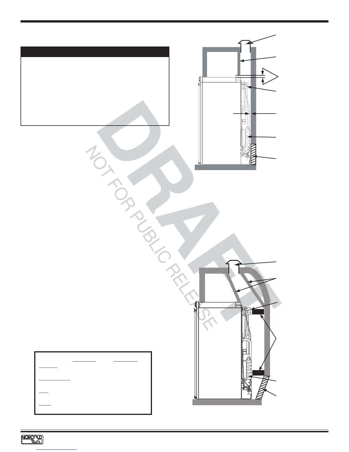
Figure 13. Roof vented ventilation arrangement
Table 1. Clearances for roof vented installations
Minimum Maximum
Bottom 0 inch 0 inch
Sides (each) 0 inch 1/8 inch
Top 0 inch 1/4 inch
Rear 0 inch 1 inch
Condenser
Roof exhaust ven
Baffle (full width
of enclosure)
required to isolate
top of refrigerator
from rejected heat
Absorber coils
1 inch maximum
(if wider see
Figure 14)
Air intake vent
1/4 inch or less
Vertical Angled Baffles
Vertical angled baffles are required when the roof
exhaust vent is installed inboard of the condenser.
Figure 14 shows the angled vertical baffles required on
inboard roof vent installations. The horizontal wall
baffles are required whenever the distance between the
cooling unit and the interior surface of the outside wall
exceeds one inch.
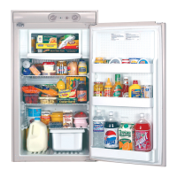
Figure 14. Roof vented ventilation with roof vent
inboard of condenser
Angled baffles--
required when
the roof vent is
inboard of the
condenser
Horizontal baffles--
required only when
opening between
outside wall and
cooling unit is
over 1 inch
Air intake vent
Absorber coils
Condenser
Roof exhaust vent