DRAFT
NOT FOR PUBLIC RELEASE
43
www.norcold.com/cda N500/N510 ModelsRefrigerator Service Manual
Installation–Power Board
1. Seat the power board in the base.
2. Attach the power board and base assembly to the
refrigerator using two, 1/4 in. self-tapping hex head
screws. Do not overtighten screws.
3. Connect the wire harness connector to the power
board, terminal P1.
4. Connect the ac heater wires to terminals AC_HI and
AC_LO.
5. Position and align the power board cover over the
power board. Attach the cover using three, 1/4 in.
self-tapping hex head screws. Do not overtighten
screws.
6. Connect the solenoid gas valve wires to terminals
GV and GV_GND.
7. Connect the spark/sense electrode wire to the power
board high tension terminal.
3-way refrigerators (AC/LP/DC)
a. Connect the DC heater wires to power board
terminals FLP/DC HEAT and DC_HT GND.
8. Connect the ac power cord to the power board.
9. Plug ac power cord into the RV ac receptacle.
10. Connect positive and the negative dc power wire
leads to the power board.
T Positive wire (+) to terminal 12VDC.
T Negative wire (–) to terminal 12_VGND1.
11. Turn ON the RV dc power to the refrigerator.
12. Turn ON refrigerator, then check all power board
control functions before placing in service.
13. Place refrigerator in service.
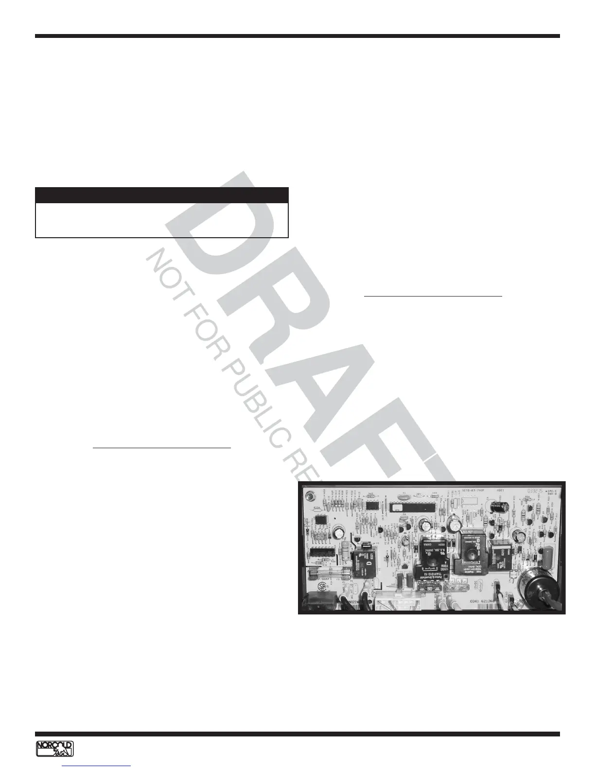
The power board is located on the back of the
refrigerator below the absorber coils. It is seated on an
insulated base to prevent the printed circuit from making
contact with the refrigerator cabinet’s metal plate. The
N510 power board, seated in its base, is shown in
Figure 38.
Two self-tapping 1/4 inch hex head screws hold the
power board and base in place. The power board cover
is held by three self-tapping 1/4 inch hex head screws.
Removal–Power Board
1. Turn OFF the refrigerator.
2. Turn OFF the RV dc power to the refrigerator.
3. Disconnect dc power supply wires from power board
terminals 12 VDC and 12_VGND1.
3-way refrigerators (AC/LP/DC)
a. Disconnect the DC heater wires from terminal
FLP/DC HEAT and DC_HT GND.
4. Unplug the ac power cord from the RV ac
receptacle.
5. Disconnect the ac cord from the power board.
6. Disconnect the gas valve wires from power board
terminals GV and GV_GND.
7. Disconnect the spark sense electrode wire.
8. Remove the three 1/4 inch self-tapping hex head
screws from the power board cover.
9. Remove the power board cover.
10. Disconnect the ac heater wires from power board
terminals AC_HI and AC_LO.
11. Disconnect the wire harness connector from power
board, terminal P1.
12. Remove the two 1/4” hex head screws attaching the
board to the base, then remove the power board
along with its base.
Power Board - N510 Models
Description
Inputs, outputs, monitoring, and diagnostic functions are
managed and controlled by the power board. Inputs,
outputs, monitoring information, and diagnostic
functions are communicated through the optical control
assembly. The wire harness interfacing the power board
with the optical control assembly is "foamed" into the
cabinet. Wiring pictorials and schematics can be found
on pages 54 and 55.
Figure 38. N510 Power Board
Because the wire harness is "foamed" into the cabinet,
it is not a replaceable component.
NOTE
ELECTRONIC COMPONENTS - N510 MODELS