DRAFT
NOT FOR PUBLIC RELEASE
12
www.norcold.com/cda
N500/N510 Models
Refrigerator Service Manual
The following procedure and troubleshooting chart
check the operation of the thermocouple and the
interrupter.
Interrupter Voltage Output Check
1. Remove refrigerator from enclosure.
2. Remove upper shroud (four screws).
3. Connect an alternate LP gas supply. Gas pressure
must be between 10.5 and 11.5 in. water column.
4. Set selector knob to LP gas operation.
5. Set temperature control knob to 5.
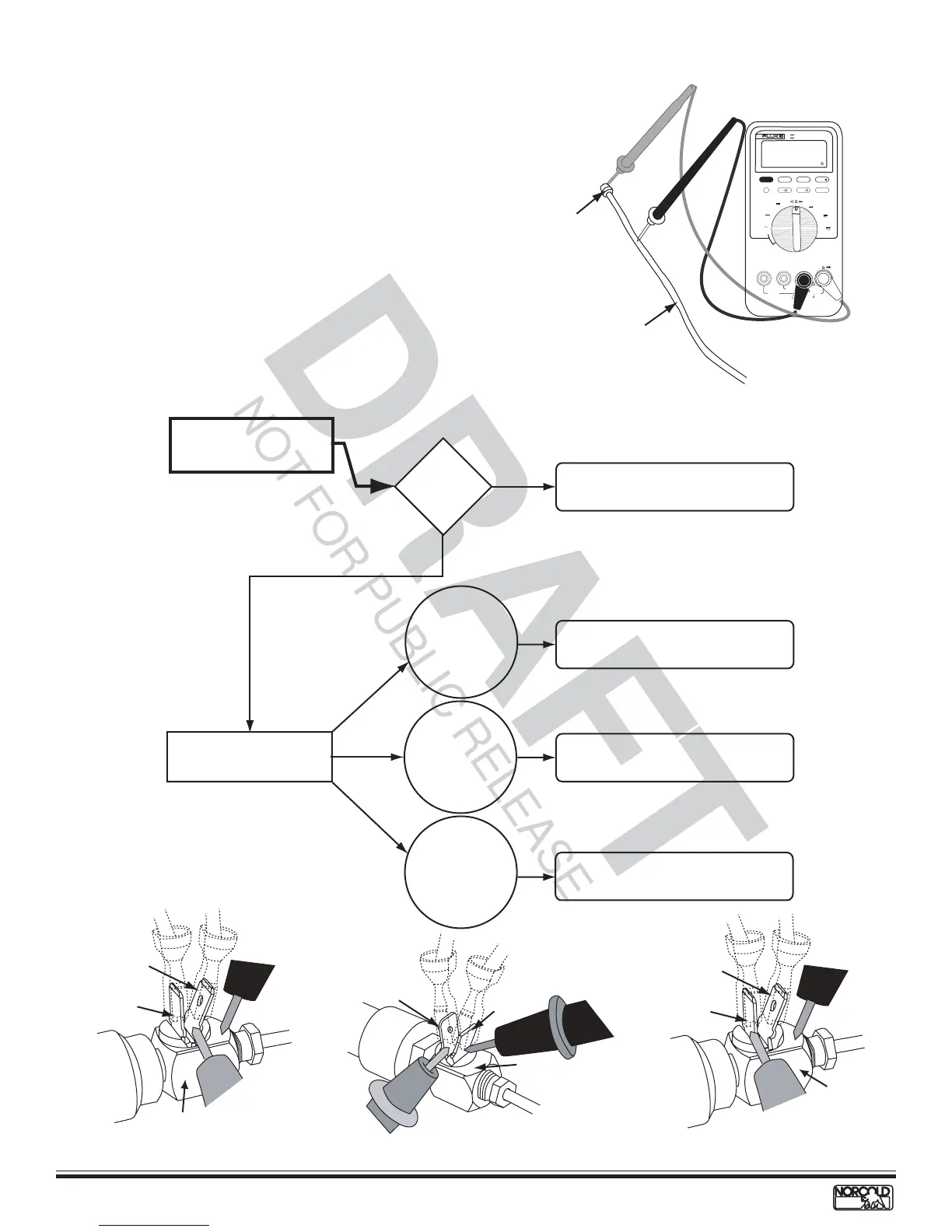
6. Connect voltmeter as shown in Figure 4. Do not
disconnect wires from interrupter.
7. Press and hold gas safety valve and turn selector
knob to LP to ignite burner. Hold the valve open to
maintain the flame lit while following procedure
below.
Replace gas safety valve. See page 24.
Check thermocouple voltage
output to interrupter.
Replace thermocouple.
Check control switch connections.
10-30 mlV
across interrupter
terminals.
See Figure 6.
No voltage (0)
reading from
straight interrupter
terminal to ground.
See Figure 7.
YES
Voltage
10 to 30
mlV?
Replace thermocouple.
NO
Check thermocouple
voltage output. See
Figure 4.
No voltage (0)
reading from
angled interrupter
terminal to ground.
See Figure 5.
Figure 6. Checking voltage across
terminals
Figure 5. Checking angled terminal
to ground
Figure 7. Checking straight
terminal to ground
Thermocouple and Interrupter Malfunctioning - N500 Units
Figure 4. Checking thermocouple voltage output to
interrupter
MIN MAX RANGE HOLD
H
HzREL
mA
A
mV
V
V
OFF
!
!
A
COM
V
mA µA
1000V MAX
400mA MAX
FUSED
10A MAX
FUSED
PEAK MIN MAX
µA
CAT II
4 1/2 DIGITS
1 Seconds
87
TRUE RMS MULTIMETER
III
Insulator
Thermocouple
Angled
terminal
Straight
terminal
Interrupte
Angled
terminal
Straight
terminal
Interrupter
Angled
terminal
Straight
terminal
Interrupter