DRAFT
NOT FOR PUBLIC RELEASE
24
www.norcold.com/cda
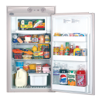
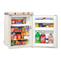
N500/N510 Models
Refrigerator Service Manual
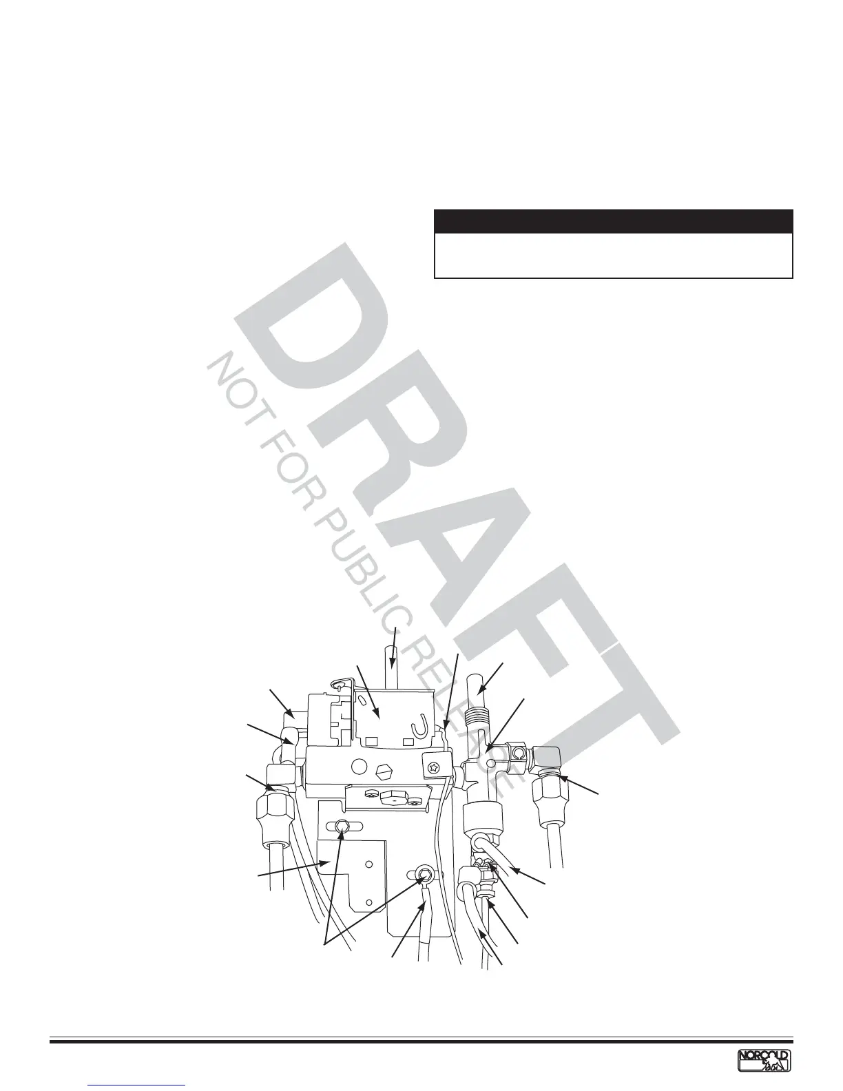
Gas Safety Valve
The gas safety valve is mounted on the control panel in
the gas valve-thermostat assembly. This valve is
designed to stop the flow of LP gas to the burner when
a flame failure occurs. Its operation is controlled by the
thermocouple, which connects directly to the gas valve’s
interrupter. During the ignition process, the valve button
must be held in (open) until a flame is established at the
burner. See Figure 20.
Gas Safety Valve Replacement
Refer to Figure 20 for locations of components.
1. Turn OFF refrigerator.
2. Unplug ac power cord.
3. Disconnect 12 Vdc supply.
3. Disconnect LP gas supply.
4. Remove screws from back mounting flange (if
present).
5. Remove retaining screws located on the front of
breaker (will need to open door to remove).
6. Remove refrigerator from enclosure.
7. Remove wiring shroud (four screws).
8. Remove thermostat knob.
9. Remove gas valve-thermostat retaining screws (2).
10. Mark interrupter wiring for ease of reinstallation
11. Remove red and blue switch leads.
12. Disconnect thermocouple.
18. Install adapter.
19. Reconnect interrupter.
20. Reconnect thermocouple.
21. Reconnect red and blue switch leads and blue flame
indicator lead to interrupter.
22. Install gas valve-thermostat assembly and retaining
screws.
23. Replace thermostat knob.
24. Replace wiring shroud.
25. Install refrigerator in enclosure.
26. Install front breaker retaining screws.
27. Install back mounting flange screws.
28. Reconnect RV LP gas supply.
29. Reconnect 12 Vdc power supply.
30. Plug in ac power cord.
31. Place refrigerator in service.
13. Remove interrupter
14. Remove adapter.
15. Disconnect gas outlet.
16. Disconnect gas safety valve from thermostat
assembly.
17. Apply sealant to switch outlet threads.
NOTE
Make sure sealant does not extend beyond the threads
and onto the valve nipple.
Figure 20. Gas valve - thermostat assembly
Gas safety
valve
Thermostat
control switch
Gas inlet
Gas outle
Interruptor
Red wire
from switch
to interruptor
Blue wire
from interruptor
to switch
Ground
wire (green)
Mounting
bracket
Bracket
retaining
screws
Brown wire
(to ac heater)
Black wire
(from switch)
Capillary
tube
Thermostat
knob shaft
Valve
button
Thermocouple
A