10
www.norcold.com
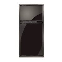
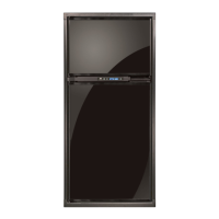
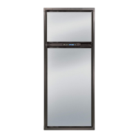
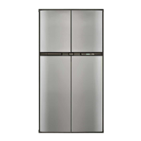
Polar Series N7V, N7X, N7XL / N8V, N8X, N8XL
Ventilation
Overview
The installed unit must
be completely
isolated from the combustion system of the
refrigerator and it must have complete and
unrestricted ventilation of the ue exhaust
which, in gas mode, can produce carbon
monoxide. The breathing of carbon monox-
ide fumes can cause dizziness, nausea, or
in extreme cases, death.
Certied installation needs one lower intake vent and one upper
exhaust vent. Install the vents through the side wall of the vehicle
exactly as instructed in the Installation Manual. Any other installa-
tion method voids both the certication and the factory warranty of
the refrigerator.
The bottom of the opening for the lower intake vent, which is also
the service access door, must be even with or immediately below
the oor level. This allows any leaking propane gas to escape to
the outside and not to collect at oor level.
American Gas Association/Canadian Gas Association (AGA/CGA)
certication allows the refrigerator to have zero (0) inch minimum
clearance at the sides, rear, top, and bottom. While there are no
maximum clearances specied for certication, the following maxi-
mum clearances are necessary for correct refrigeration:
Bottom 0 inch min. 0 inch max.
Each Side 0 inch min. 1/4 inch max.
Top 0 inch min. 1/4 inch max.
Rear 0 inch min. 1 inch max.
These clearances plus the lower and upper vents cause the natural
air draft that is necessary for good refrigeration.
Cooler air goes in through the lower intake vent, goes around the
refrigerator coils where it removes the excess heat from the refrig-
erator components, and goes out through the upper exhaust vent.
If this air ow is blocked or decreased, the refrigerator may not cool
correctly.
Each NORCOLD model is certied by AGA and CGA for correct
ventilation.
ATTENTION
!
ATTENTION
!
ATTENTION
!
ATTENTION
!
To conrm that installation is adequate, check for:
■ Adequate ventilation - refer to "Ventilation Requirements" in the
refrigerator Installation Manual.
■ Both gas and electrical components installed and operating in a
safe condition.
■ Adequate seal between refrigerator mounting ange and cut-out
opening.
■ Installed on a solid oor (not on carpet) and secured.
This refrigerator is not intended to be
operated as a free standing unit (i.e.
where the products of combustion are not
completely isolated from the living area) or
installed in such a way as to conict with
these installation instructions. Unapproved
installations could result in safety risks or
performance problems.
ATTENTION
!
Enclosure
The cabinet that encloses the refrigerator is built by the RV manu-
facturer. Depending on cabinet depth, height, and width certain
bafes may be present when cabinet clearances exceed installa-
tion guidelines and specications.
Bafes
Bafes prevent hot air buildup “pocketing” between the refrigerator
cabinet and the enclosure walls and/or ceiling. An enclosure may
be tted with:
■ An absorber bafe and a condenser bafe
■ Side bafes (Fig. 6, A)
■ Vertical top bafe (Fig. 6, B)
■ Vertical angled bafes
■ Box bafe
■ Or a combination of any of the above
For complete detail about any necessary bafe(s), refer to the
refrigerator Installation Manual.
Lower Intake Vent
Ventilation and combustion air ow through the lower intake vent
(Fig. 6, C), which also serves as the service access or door. The
lower intake vent needs be kept clear of obstructions that may
restrict the ow of fresh air into the enclosure.
Exhaust Vent
Warm air and combustion gases ow out of the enclosure through
the exhaust vent. The exhaust vent can be either a roof exhaust
vent (Fig. 6, D) or an upper sidewall exhaust vent.
The roof exhaust vent has a non-removable metal mesh screen
to prevent leaves, birds, rodents and/or debris from entering the
enclosure.
Roof Cap
The roof cap (Fig. 6, E) ts over exhaust vent. The sloped end
always faces the front of the RV. It is held in place by four (4) 2-1/2”
long Phillips head screws.
GENERAL INFORMATION
 Loading...