SK 500E – Brief instructions for frequency inverters
30 BU 0540 EN-1516
Incremental encoder
According to the resolution (pulse number), incremental encoders generate a defined number of
pulses for each rotation of the encoder shaft (Track A / Track A inverse) With this, the precise speed
of the encoder or motor can be measured by the frequency inverter. By the use of a second track (B /
B inverse) shifted by 90° (¼ period), the direction of rotation can also be determined.
The supply voltage for the encoder is 10-30V. The voltage source can be an external source or the
internal voltage (according to the frequency inverter version: 12 V /15 V /24 V).
Special terminals are available for connection of a rotary encoder with TTL signals. Parameterisation
of the corresponding functions is made with the parameters from the group "Control parameters"
(P300 et seq.) TTL encoders enable the best performance for control of a drive unit with frequency
inverters SK 520E and above.
The digital inputs DIN 2 and DIN 4 are used to connect an encoder with an HTL signal.
Parameterisation of the corresponding functions is carried out with parameters P420 [-02/-04] or P421
and P423 as well as P461 – P463. In contrast to TTL encoders, HTL encoders only enable restricted
performance for speed control (lower limit frequencies). However, they can be used with a
considerably lower resolution and also for SK 500E
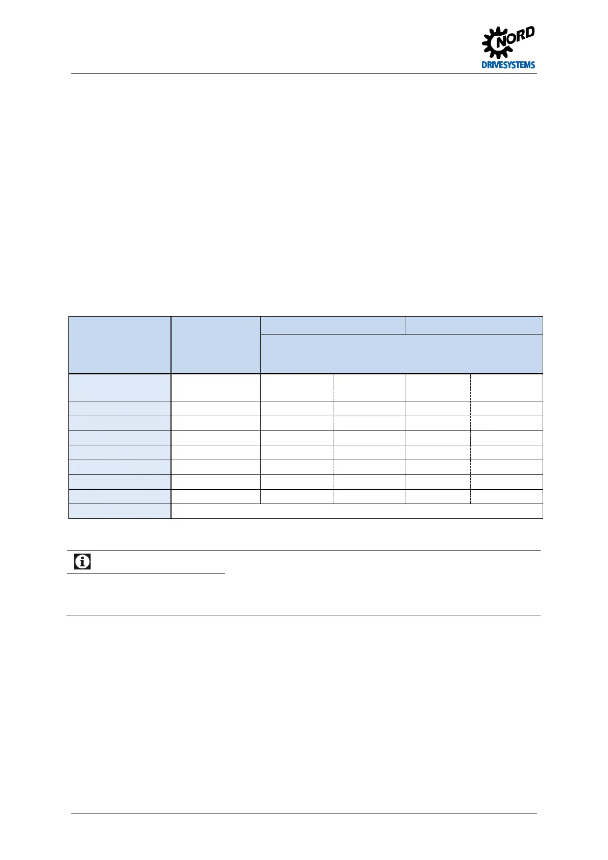
Function
Cable colours,for
incremental
encoder
Signal type TTL Signal type HTL
Assignment for SK 5xxE
Terminal block X5 or X6
10-30 V supply brown / green
42(/44 /49)
/12V)
/12V)
0 V supply white / green
GND/0V
GND/0V
Track A inverse green
ENC A- - -
Track 0 red
- - -
Cable shield Connected to a large area of the frequency inverter housing or shielding angle
Table 7: Colour and contact assignments for NORD – TTL / HTL incremental encoders
Information
Incremental encoder data sheet
If the equipment deviates from the standard equipment (Type 5820.0H40, 10-
30V encoder, TTL/RS422 or
encoder type 5820.0H30, 10-30V encoder, HTL) for the motors, please note the accompanying data sheet or
consult your supplier.
Pos: 10 6 /Anlei tung en/El ektr onik/FU und Star ter/3 . Anzei ge, Be dienu ng und Op tione n/SK 5xxE/3 . Anzeig e und Bedi enu ng @ 0\mod_1327492711496_388.docx @ 6260 @ 1 @ 1
 Loading...

