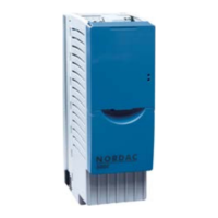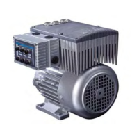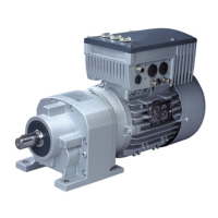
Do you have a question about the Nord Drivesystems SK 535E Series and is the answer not in the manual?
| Brand | Nord Drivesystems |
|---|---|
| Model | SK 535E Series |
| Category | DC Drives |
| Language | English |
Provides essential safety and usage guidelines for electronic drive technology.
Covers the installation and cooling requirements for the equipment.
Instructions for safe and compliant electrical connections.
Guidance on maintenance, repairs, and handling of components.
Specifies the intended use of SK 500E inverters and compliance with directives.
Defines the meaning of various danger, warning, and caution labels used in the document.
Lists critical safety notes, particularly concerning electric shock hazards.
Covers electrical hazards from voltage supply and earthing faults.
Warns about potential injuries from unexpected motor starts.
Lists the standards and directives that the SK 200E series devices comply with.
Illustrates and specifies the minimum mounting distances for proper ventilation.
Highlights severe electrical dangers during connection and emphasizes earthing.
Information on connecting the mains, motor, and braking resistor.
Details cable cross-sections, AWG, and tightening torques for connections.
Explains mains connection requirements, including fuses and circuit breakers.
Specifies motor cable length limits and requirements for screened cables.
Explains control connection locations and data for various inverter sizes.
Details color codes and terminal assignments for TTL and HTL encoders.
Details normal field bus protocols like AS Interface, CANopen, DeviceNet, etc.
Details the procedure for installing specific technology units like SK TU4-PNT.
Warns about live voltages present during commissioning.
Explains pre-programmed settings and inputting motor data.
Details the minimum connections for controlling the inverter via digital and analog inputs.
Covers essential inverter settings like start-up, deceleration, and frequency limits.
Covers parameters for motor-specific data, current control, and boost settings.
Details control parameters specific to encoder input for SK 520E/530E.
Lists detailed parameters for positioning points, window, and hysteresis.
Details parameters for position control, encoder setup, and position points.
Describes how warning messages are generated and displayed.
Explains how errors cause switch-off and options for resetting faults.
Explains the meaning of the green and red LEDs indicating device status.
Lists common error codes, their causes, and recommended remedies.
Details specific error messages related to temperature, motor, and brake resistor.
Explains the I't overcurrent limit error and its causes.
Explains mains phase errors due to connection or network asymmetry.
Details overcurrent module errors, motor cable issues, and choke usage.
Details parameter loss errors due to EEPROM issues or EMC interference.
Explains overvoltage errors and recommended actions like adjusting deceleration.
Covers various EEPROM errors including KSE, internal, and copy issues.
Details charging errors related to low link circuit voltage or mains undervoltage.
Details bus timeout errors for CAN/CANopen and general system errors.
Details key specifications like output frequency, overload capacity, and insulation.


