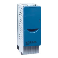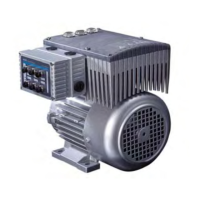
Do you have a question about the Nord Drivesystems SK 511E Series and is the answer not in the manual?
| Series | SK 511E |
|---|---|
| Category | DC Drives |
| Protection Class | IP20 |
| Communication Interfaces | CANopen |
| Ambient Temperature | 0°C to +40°C |
Provides a general overview of the SK 500E frequency inverter properties.
Details essential safety and installation guidelines for the device.
Specifies the intended application and usage of the SK 500E frequency inverter.
Covers all aspects of connecting the frequency inverter electrically.
Explains the meaning of DANGER, WARNING, CAUTION, NOTICE, and Note labels.
Provides specific safety notes related to electric shock hazards.
Highlights immediate dangers from electric shock due to live components.
Warns about electric shock from voltage supply and motor starting injuries.
Describes how to use mounting brackets and the correct vertical installation position.
Emphasizes the mandatory earthing and electrical safety precautions for devices.
Details the various terminal blocks and their functions for power connections.
Provides guidelines for ensuring electromagnetic compatibility through proper wiring.
Specific advice on routing and shielding control cables to prevent interference.
Explains how to adapt the inverter for IT network operation using jumpers or DIP switches.
Illustrates jumper settings for network input (IT/normal) for sizes 1-7.
Explains IT network adaptation using DIP switches for inverters above size 8.
Covers mains, motor, and brake resistor connections, including cable requirements.
Advises on motor cable length limits and the use of output chokes.
Details terminal connections for the control unit across different inverter sizes.
Describes the analog input/output terminal block X4 and its designations.
Details the function, data, and parameters for digital inputs 1-5.
Details functions and parameters for digital inputs 1-5, and thermistor evaluation.
Details connections and assignments for incremental encoders (TTL/HTL).
Details the terminals and connections for CAN and CANopen communication.
Details terminals and connections for RS485 and RS232 communication.
Explains encoder connection, counting direction, and functional tests.
Describes encoder functionality, signal types (TTL/HTL), and voltage supply options.
Outlines the initial steps after connecting power supply for inverter operation.
Explains the importance of inputting motor data and using factory settings for standard applications.
Details parameters for motor-specific data, current control, and characteristic curves.
Details control parameters specific to encoder input for SK 520E/53xE.
Explains how error messages cause shutdown and lists options for fault reset.
Details how errors are displayed via SimpleBox/ControlBox and stored in parameters.
Lists specific error codes (E001, E002) with their causes and recommended remedies.
Details errors related to overcurrent, chopper overtemperature, and IGBT overcurrent.
Covers errors related to overvoltage, charging errors, and undervoltage.
Lists errors related to EEPROM data, type, copying, and size.


