2 Assembly and installation
BU 0540 EN-1516 25
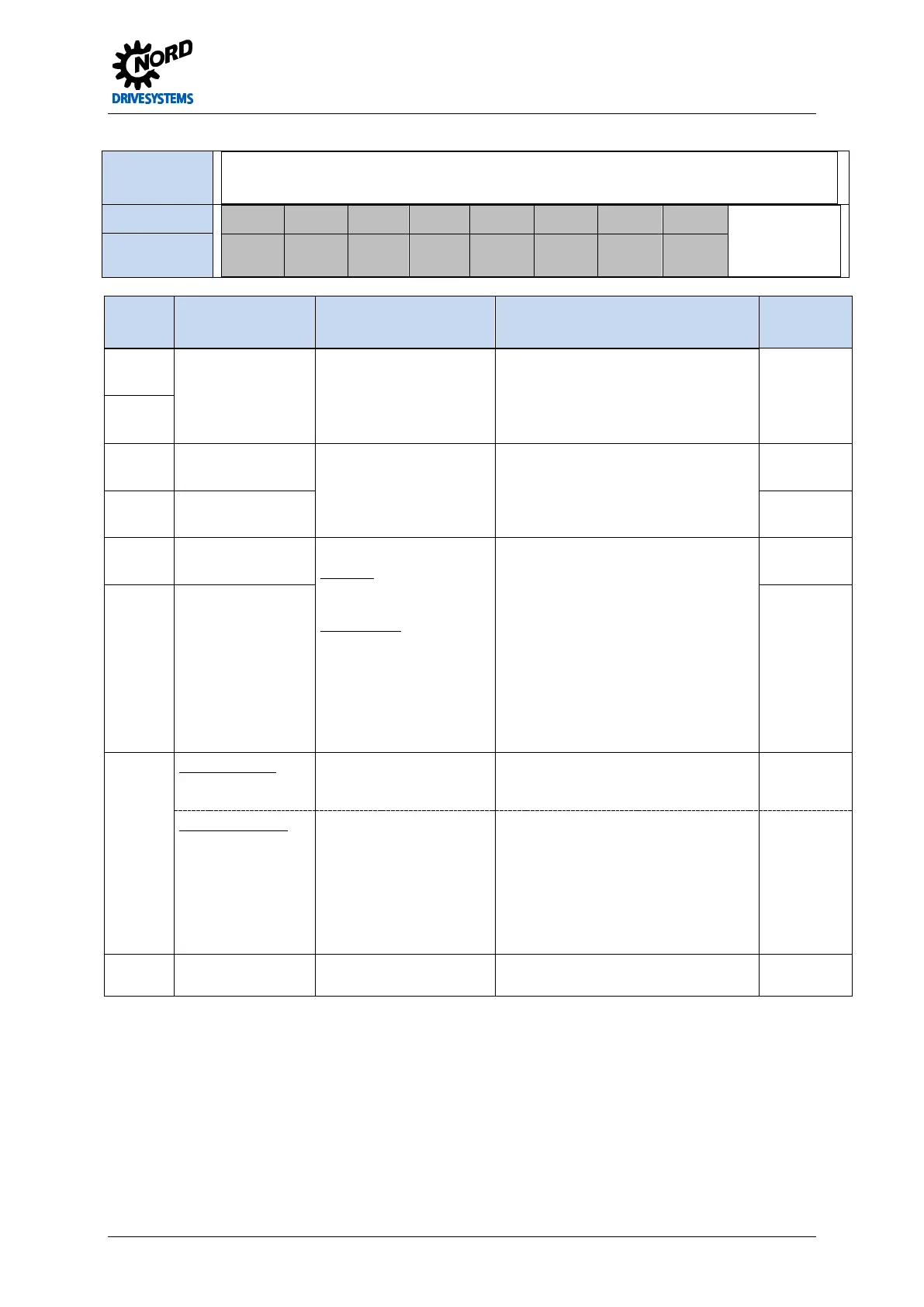
Relevance
SK 500E SK 505E SK 510E SK 511E SK 515E SK 520E SK 530E
SK 535E
√
Terminals X7:
73 74 26 27 5 7 44* 40
* Terminal 44:
up to Size 4: VI
Size 5 and above:
VO
RS485
+
RS485 - DIN6 DIN7 DOUT1 DOUT2 V…24V GND/0V
Designation
Terminal Function
[factory setting]
Data Description / wiring suggestion Parameter
73
Data cable RS485
Baud rate
9600…38400Baud
Termination resistor
R=120Ω
BUS connection parallel to RS485 on
RJ12 plug
NOTE: The termination resistance of
DIP switch 1 (see RJ12/RJ45) can also
be used for terminal 73/74.
P503
P509
74
26 Digital input 6
[no function]
7.5...30V, R
i
=3.3kΩ
As described for terminal block X5, DIN1
to DIN5.
Not suitable for the evaluation of a motor
thermistor.
P425
27 Digital input 7
[no function]
P470
5 Output 3 (DOUT1)
[no function]
Digital output
S1 to S4
18-30V, according to VI
24V, max. 20 mA
above Size 5
DOUT1 and DOUT2:
24V, max. 200 mA
With inductive loads:
provide protection via free-
wheeling diode.
For evaluation in a control system. The
scope of functions corresponds to that of
the relay (P434).
P450
7 Output 4 (DOUT2)
[no function]
P455
44 Size 1 to Size 4
VI 24V supply
voltage input
18…30V
min. 800 mA (input)
Voltage supply for the FI control unit. Is
essential for the function of the
frequency inverter.
Size 5 and above
VO 24V supply
voltage output
24V ± 25%
max. 200 mA (output)
short circuit resistant
Supply voltage provided by the
frequency inverter for connection to the
digital inputs or the supply of a 10-30V
encoder.
The 24V control voltage is generated by
the FI, however it can also be supplied
via the terminals X12:44/40. Supply via
terminal X7:44 is not possible.
40 Reference potential
for digital signals
0V digital
Pos: 89 /Anlei tunge n/Ele ktro nik/FU und Start er/2. Mont age und Ins tall ation/ Ele ktrisc her Ansc hluss /SK 50 0E/2.1 0.5 Ele ktris cher Ansc hluss St euert eil- S tec ker bloc k X 9 u nd X 10 – CAN / CANopen [SK 500...535E] @ 1\mod _1341402404239_388.docx @ 29385 @ 5 @ 1
 Loading...

