2 Assembly and installation
BU 0540 EN-1516 19
NOTICE
Operation in IT networks
The use of this frequency inverter on an IT network is possible after modification of the integrated mains filter.
It is urgently recommended that the frequency inverter is only operated on a IT network if a braking resistor is
connected. If an earthing fault occurs in the IT network, this measure prevents an impermissible charging of the
link circuit capacitor and the associated destruction of the frequency inverter.
For operation with an insulation monitor, the insulation resistance of the frequency inverter must be taken into
account.
Pos: 73 /Anlei tunge n/Ele ktro nik/FU und Start er/2. Mont age und Ins tall ation/ Ele ktrisc her Ansc hluss /SK 50 0E/2.1 0.4 Ele ktris cher An schl uss Leis tungst eil -Teil 2 - M otor kab el ( X2) [BU 0 500] @ 1\ mod_1331195941727_388.docx @ 17638 @ 5 @ 1
Motor cable (X2 - U, V, W, PE)
The motor cable may have a total length of 100m if this is a standard cable (take EMC into
consideration). If a screened motor cable is used, or if the cable is laid in a metal conduit which is well
earthed, the total length should not exceed 30m.
For greater lengths of cable, an additional output choke (accessory) must be used.
For multiple motor operation the total motor cable length consists of the sum of the individual cable
lengths.
NOTICE
Output switching
The motor cable must not be switched as long as the inverter is pulsing (The inverter must be in "Standby" or
"Starting disabled" status).
Otherwise the inverter nay be damaged.
Pos: 74 /Anlei tunge n/Ele ktro nik/FU und Start er/2. Mont age und Ins tall ation/ Ele ktrisc her Ansc hluss /SK 50 0E/2.1 0.4 Ele ktrischer Anschluss Leist ungsteil -Teil 3 - Bremswiderstand (X2) [BU 0500] @ 1\mod_1331195973501_388.docx @ 17662 @ 5 @ 1
Breake resistor (X2 - +B, -B)
The terminals +B/ -B are intended for the connection of a suitable braking resistor. A short screened
connection should be selected. For the installation of a braking resistor, the large amount of heat
which is generated due to its operation (> 70°C) must be taken into account.
Pos: 75 /A nl eitu nge n/El ek tro nik/FU u nd S tart er/ 2. M o ntag e un d Ins tall ati on/ El ektri scher Ansc hluss/S K 500 E/2.10. 5 Elek trisch er Ans chluss Steuer teil [ BU 0500] @ 0\mod_1325864707420_388.docx @ 6124 @ 3 @ 1
2.2.4 Electrical connection of the control unit
The control connections are located under the front cover (above size 8 under the two front covers) of
the frequency inverter. The configuration differs according to the size. Up to size 7, the individual
control terminals (X3, X8, X13) are in staggered positions (please see chapter 2.2 "Electrical
connection").
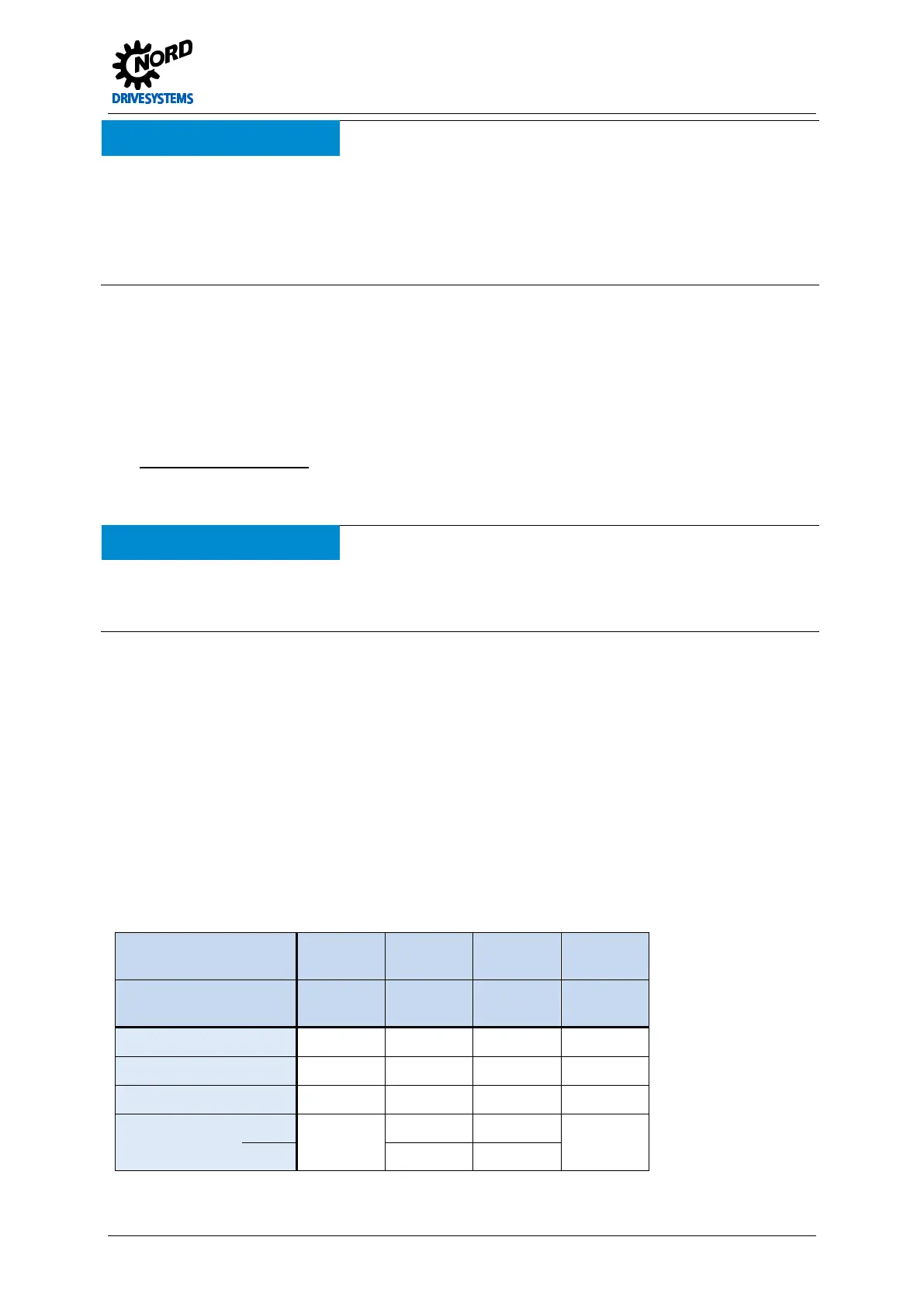
Connection data:
Frequency inverter All Size 1 … 4 Size 5 … 7
Above
size 8:
Terminal block Typically X3
X12, X13
X15
Rigid cable Ø [mm²] 0.14 … 1.5 0.14 … 2.5 0.2 … 6 0.2 … 2.5
Flexible cable Ø [mm²] 0.14 … 1.5 0.14 … 1.5 0.2 … 4 0.2 … 2.5
AWG standard 26-16 26-14 24-10 24-12
Starting torque [Nm] Clamping 0.5 … 0.6 0.5 … 0.6 Clamping
[lb-in] 4.42 … 5.31 4.42 … 5.31
 Loading...

