SK 500E – Brief instructions for frequency inverters
20 BU 0540 EN-1516
GND/0V is a common reference potential for analog and digital inputs.
Furthermore, it must be taken into account that with SK 5x5E size 1 ... 4 frequency inverters, terminal
44 is used to feed in the control voltage. However with devices of size 5 and above, this terminal
provides a 24V control voltage.
5 V / 15 V (24 V) can be obtained from several terminals if required. This also includes e.g. digital outputs or a
operating module connected via RJ45
With size 1 ... 4, the total output current must not exceed 250 mA / 150 mA (5 V / 15 V). Above Size 5 the limiting
value is 250 mA / 200 mA (5 V/24 V).
Pos: 76 /A nl eitu nge n/El ek tro nik/FU u nd S tart er/ 1. Allg emei n es/Si ch erhei ts- und Inst all ati onshi n weis e/Si cher hei tshi n weis e/ver sc hie den e/Ac ht ung - Kab elführ ung @ 7\mod_1434636821334_388.docx @ 227185 @ @ 1
NOTICE
Cable laying
All control cables (including thermistors) must be routed separately from the mains and the motor cables to
prevent interference in the device.
If the cables are routed in parallel, a minimum distance of 20 cm must be maintained from cables which carry a
voltage of > 60 V. The minimum distance may be reduced by screening the cables which carry a voltage, or by
the use of earthed metal partitions within the cable conduits.
Pos: 77 /A nl eitu nge n/El ek tro nik/FU u nd S tart er/ 2. M o ntag e un d Ins tall ati on/ El ektri sc her Ansc hluss /SK 50 0E/2.1 0.5 Ele ktris cher An schl uss Ste uertei l- Kle mme nbloc k X 3 - R el ais [ SK 500 ...5 35E] @ 1\mod_1341401431286_388.docx @ 29221 @ 5 @ 1
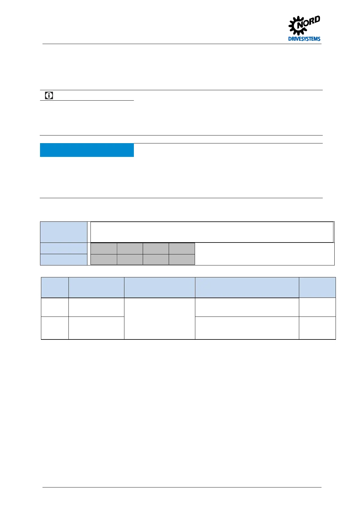
Terminal block X3, (above size 8: X3.1 and X3.2) - Relay
Relevance
SK 500E SK 505E SK 510E SK 511E SK 515E SK 520E SK 530E SK 535E
√ √ √ √ √ √ √ √
Terminals X3:
1 2 3 4
K1.1 K1.2 K2.1 K2.2
Name
Terminal Function
[Factory setting]
Data Description / wiring suggestion Parameter
1
2
Output 1
[Braking control]
Relay closing contact
230 VAC, 24 VDC,
< 60 VAC in circuits with
safe isolation,
≤ 2 A
Brake control
(closes on enabling)
P434
3
4
Output 2
[Ready/Fault]
Fault / Ready
(closes when FI ready / no fault)
P441
Pos: 79 /A nl eitu nge n/El ek tro nik/FU u nd S tart er/ 2. M o ntag e un d Ins tall ation/ Ele ktrisc her Ansc hluss /SK 50 0E/2.1 0.5 Ele ktris cher An schl uss Ste uertei l- Kle mme nbloc k X 4 – Analog I/O [SK 500...535E] @ 1\mod_1341401660718_388.docx @ 29265 @ 55 @ 1
 Loading...

