2 Assembly and installation
BU 0540 EN-1516 21
Terminal block X4 – Analog I/O
Relevance
SK 500E SK 505E SK 510E SK 511E SK 515E SK 520E SK 530E SK 535E
√ √ √ √ √ √ √ √
Terminals X4:
11 12 14 16 17
VO 10V GND/0V AIN1 AIN2 AOUT1
Name
Terminal Function
[factory setting]
Data Description / wiring suggestion Parameter
11 10V Reference
voltage
10V, 5mA,
Not short circuit resistant
The analog input controls the output
frequency of the frequency inverter.
The possible digital functions are
described in Parameter P420.
Above Size 5:
Configuration of analog input with DIP
switch (see below)
12 Reference potential
for analog signals
0V analog
14 Analog input 1
[set point frequency]
V=0...10V, R
i
=30kΩ,
I=0/4...20mA, R
i
=250Ω,
can be switched over with
DIP switch, reference
voltage GND.
For the use of digital
functions 7.5...30V.
Above Size 5:
also -10 … + 10 V signals
P400
16 Analog input 2
[no function]
P405
17 Analog output
[no function]
0...10V
Reference potential GND
Max. load current:
5mA analog,
20mA digital
Can be used for an external display or
for further processing in a following
machine.
P418
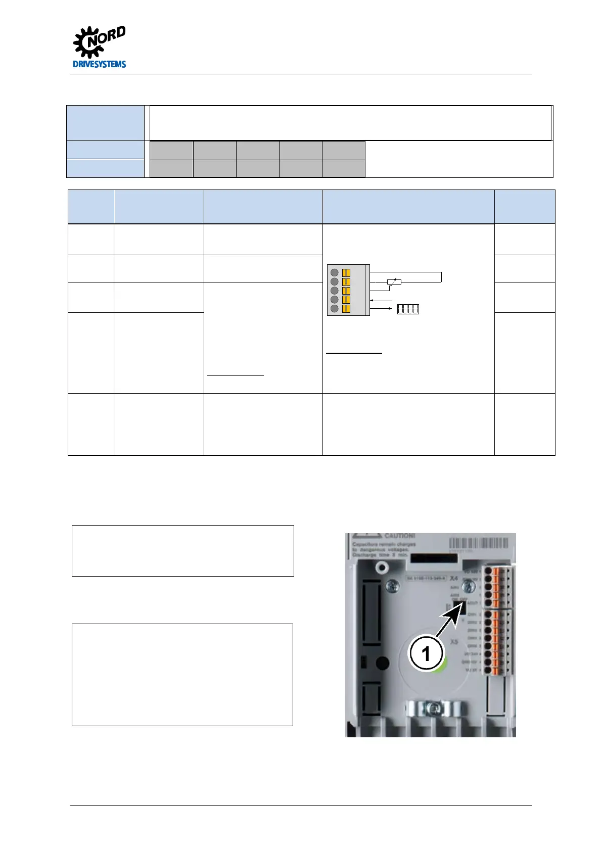
Analog signal configuration
Size 1 … 4
1 = DIP switch: left = I / right = V
V = Voltage
Above Size 5:
1 = DIP switch: left = ON / right = OFF
I = ON = current 0/4...20 mA
= ON = current 0/4...20 mA
Note:
If S2 = ON (AIN2 = Current input), S4 must be = OFF.
If S1 = ON (AIN1 = Current input), S3 must be = OFF.
 Loading...

