2 Assembly and installation
BU 0540 EN-1516 29
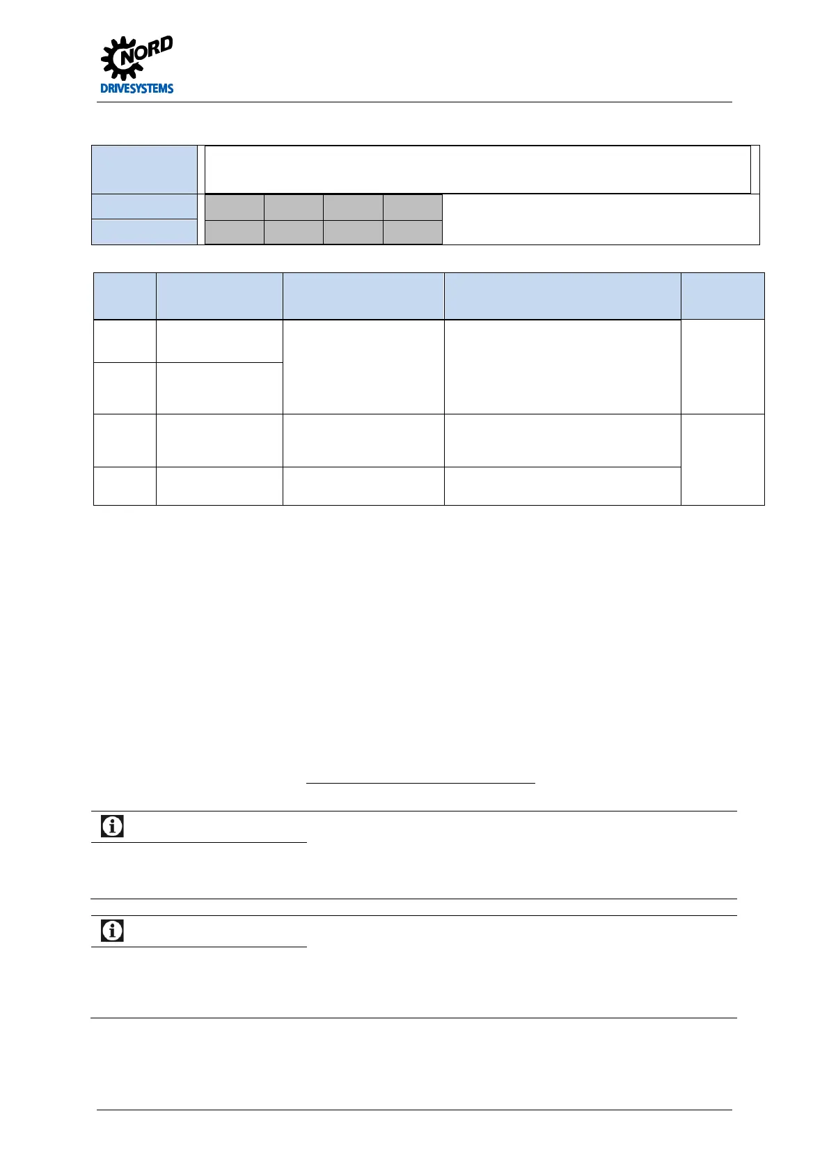
Terminal block X15 – motor PTC and 24V input (above size 8)
Relevance
SK 500E SK 505E SK 510E SK 511E
SK 515E
SK 520E SK 530E
SK 535E
√
√
Terminals X15:
38 39 44 40
T1 T2 VI 24V GND
Name
Terminal Function
[factory setting]
Data Description / wiring suggestion Parameter
38
Thermistor input +
EN 60947-8
On: >3.6 kΩ
Off: < 1.65 kΩ
Measurement voltage 5 V
at R < 4 kΩ
The function cannot be switched off, set
a jumper if no PTC is present.
39
Thermistor input -
44
Voltage supply input
24V … 30V
min. 3000mA
Voltage supply for the FI control unit. Is
essential for the function of the
frequency inverter.
40 Reference potential
for digital signals
GND/0V Reference potential
Pos: 10 0 /Anlei tung en/El ektr onik/FU und Star ter/2 . Mon tage un d Install atio n/Ele ktrisc her Ans chlus s/Dr ehgeb er/F arb- und K onta ktbeleg ung für Drehg eber [ BU 0500] @ 0\mod_1325865982124_388.docx @ 6147 @ 2 @ 1
2.3 Colour and contact assignments for encoders
Encoder input X6
The incremental encoder connection is an input for a type with two tracks and TTL-compatible signals
for EIA RS 422-compliant drivers. The maximum current consumption of the incremental encoder
must not exceed 150 mA
The pulse number per rotation can be between 500 and 8192 increments. This is set with the normal scaling via parameter
P301 "Incremental encoder pulse number" in the menu group "Control parameters". For cable lengths > 20 m and motor speeds
above 1500 rpm the encoder should not have more than 2048 pulses/revolution.
For longer cable lengths the cable cross-section must be selected large enough so that the voltage
drop in the cable is not too great. This particularly affects the supply cable, in which the cross-section
can be increased by connecting several conductors in parallel.
Unlike incremental encoders, for sine encoders or SIN/COS encoders the signals are not in the form
of pulses, but rather in the form of sine signals (shifted by 90°).
Information
Rotary encoder counting direction
The direction of rotation of the incremental encoder must correspond to that of the motor. Therefore, depending
on the rotation direction of the encoder to the motor (possibly reversed), a negative number must be set in
parameter P301.
Information
Rotary encoder function test
The voltage difference between tracks A and B can be measured with the aid of parameter P709 [-09] and [-10]. If
the incremental encoder is rotated, the value of both tracks must jump between -0.8V and 0.8V. If the voltage only
jumps between 0 and 0.8V the relevant rack is faulty. The position can no longer be reliably determined via the
incremental encoder. We recommend replacement of the encoder!
Pos: 10 1 /Anlei tung en/El ektr onik/FU und Star ter/2 . Mon tage un d Instal lati on/El ektri scher A nschl uss/Dr ehg eber/F arb- un d Kont aktbel egung für Drehg eber - Inkrementalgeber [SK 5xxE] @ 1\mod_1331216115763_388.docx @ 17854 @ 5 @ 1
 Loading...

