2 Assembly and installation
BU 0540 EN-1516 17
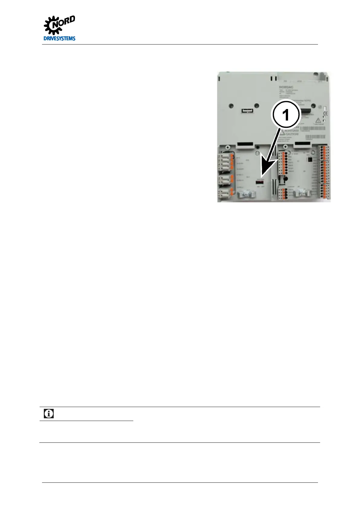
Adaptation above size 8:
Adaptation to an IT network is carried out via the DIP switch
"EMC filter" (1). As delivered, this switch is in the "ON"
position.
For operation in an IT network the switch must be set to the
"OFF" position. The leakage current
impairment of EMC compatibility.
Pos: 70 /Anlei tunge n/Ele ktro nik/FU und Start er/2. Mont age und Ins tall ation/ Ele ktrisc her Ansc hluss /SK 50 0E/2.1 0.4 Ele ktris cher Ansc hluss L eist ungstei l [BU 0 500] @ 0\mod_1325863684752_388.docx @ 6078 @ 3 @ 1
2.2.3 Electrical connection of power unit
The following information relates to all power connections to the frequency inverter. This includes:
• Mains cable connection (L1, L2/N, L3, PE)
• Motor cable connection (U, V, W, PE)
• Brake resistor connection (B+, B-)
• Link circuit connection (-DC, (+DC))
• Link circuit choke connection (-DC, CP, PE)
Before connecting the frequency inverter, the following must be observed:
1. Ensure that the mains supply provides the correct voltage and is suitable for the current required.
2. Ensure that suitable circuit breakers with the specified nominal current range are installed between
the voltage source and the inverter.
3. Connect the mains voltage directly to the mains terminals L1-L2/N-L3-PE (for each device)
4. A four-core cable must be used to connect the motor. The cable is connected to the motor
terminals PE-U-V-W.
5. If screened motor cables (recommended) are used, the cable screening must also be connected to
a large area of the metallic screening angle of the EMC Kit, however, at least to the electrically
conducting mounting surface of the control cabinet.
6. Above size 8, the cable lugs which are included in the scope of delivery must be used. After
crimping, these must be insulated with shrink hose.
Information
The use of shielded cables is essential in order to maintain the specified radio interference suppression level.
If certain wire end sleeves are used, the maximum cross-section which can be connected can be reduced.
 Loading...

