SK 500E – Brief instructions for frequency inverters
16 BU 0540 EN-1516
Adaptation for Size 1 – 7
NOTICE
Jumper positions
Jumper positions which are not illustrated below must not be used, as these may cause the destruction of the
frequency inverter.
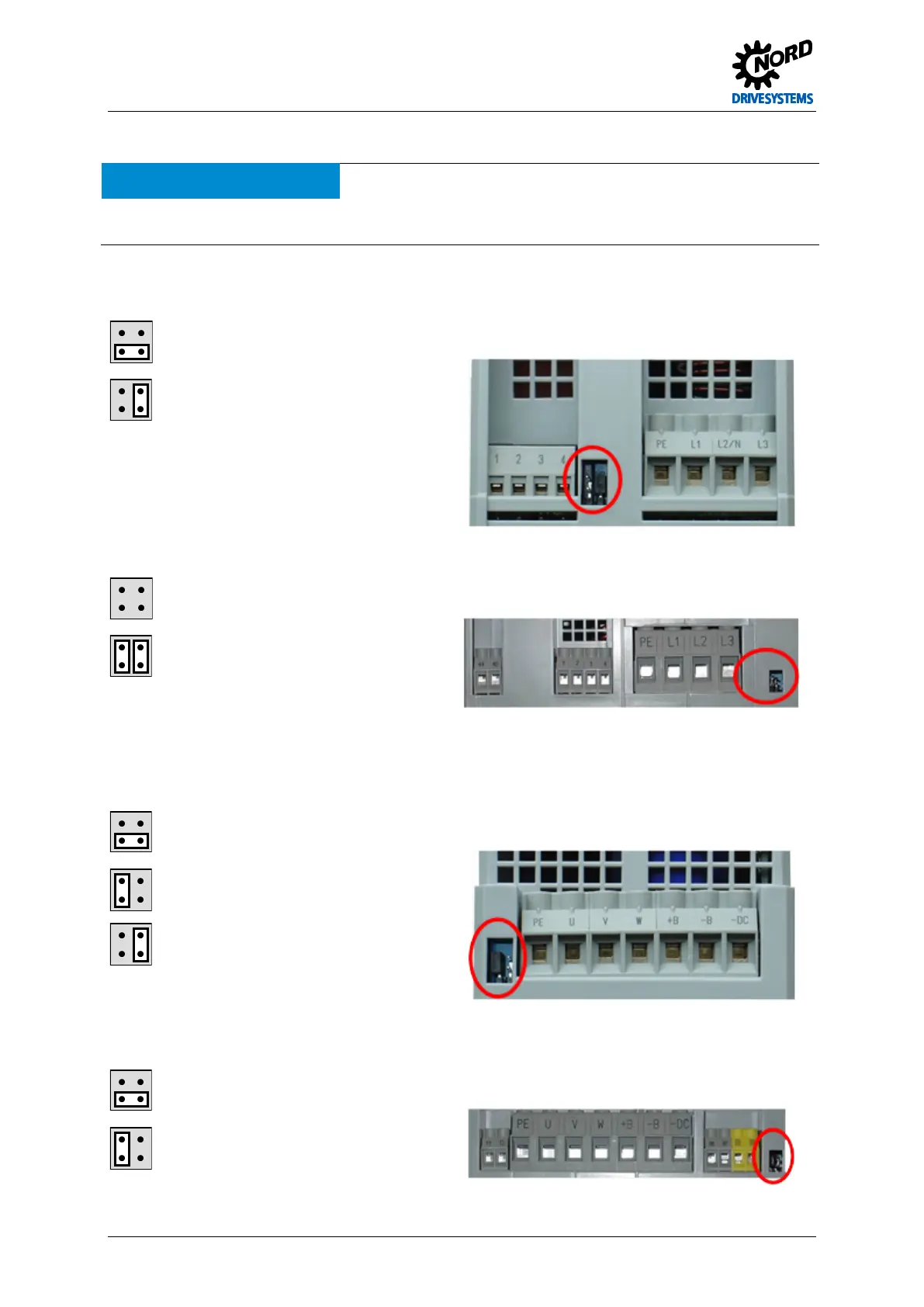
Jumper 'A’ network input (only type SK 5xxE-…-A inverters)
Size 1 – 4
Operation in IT network = Position 1
(reduced leakage current)
Top side of device
Normal position = Position 3
Size 5 – 7
Operation in IT network = Position 0
(reduced leakage current)
Top side of device
Normal position = Position 4
Jumper 'B' motor output
Operation in IT network = Position 1
(reduced leakage current)
Underside of the device
Normal position = Position 2
Reduced leakage current – Position 3
(The set pulse frequency (P504) only has a slight
influence on the leakage current.)
(for type SK 5xxE-…-O inverters the function is
identical to position 1))
Size 5 – 7
Operation in IT network = Position 1
(reduced leakage current)
Underside of the device
Normal position = Position 2
 Loading...

