SK 500E – Brief instructions for frequency inverters
14 BU 0540 EN-1516
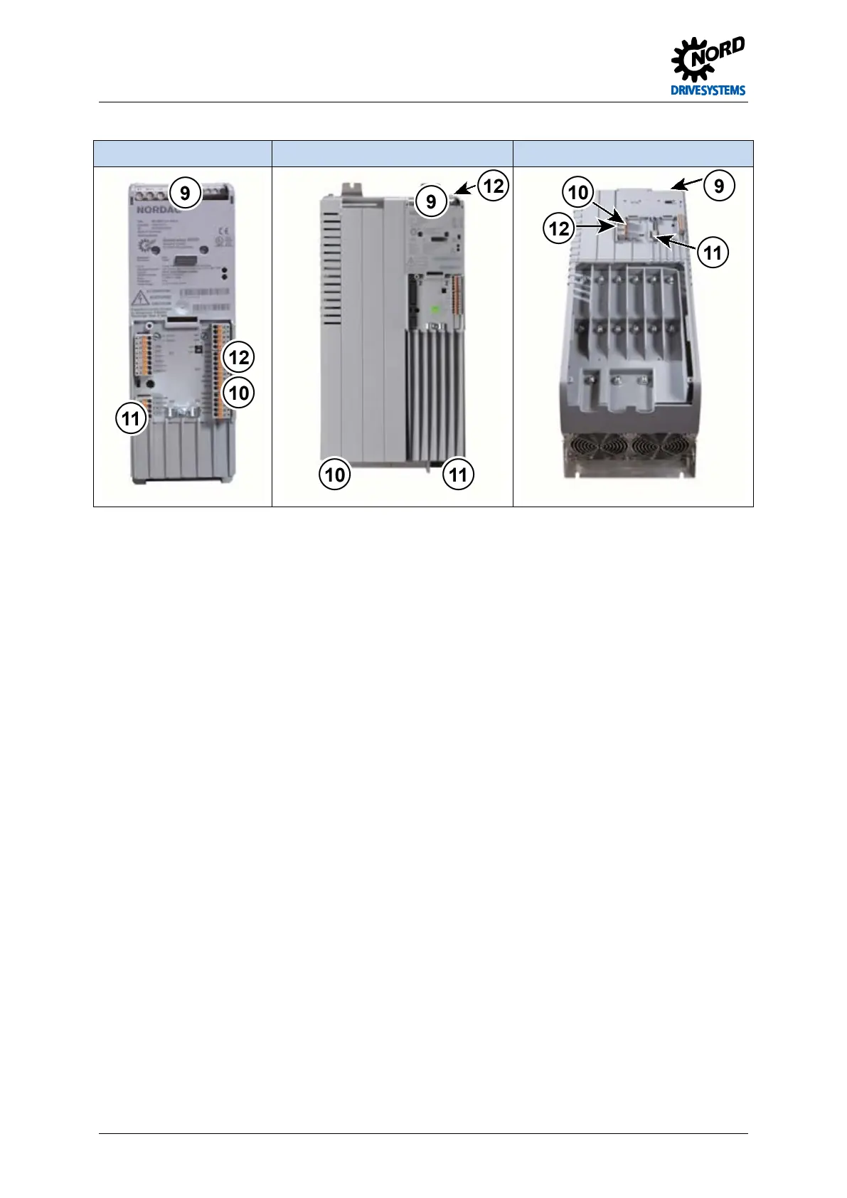
Size 1 - 4 Size 5 - 7 Above size 8
communication CAN/CANopen; RS232/RS485
X9/X10; X11
Up to size 4 (except SK 54xE): to DIN 5
Safe pulse block 86, 87, 88, 89 X8
Except SK 5x0E and SK 511E
Pos: 65 /A nl eitu nge n/El ek tro nik/FU u nd S tart er/ 2. M o ntag e un d Ins tall ati on/ El ektri sc her Ansc hlus sV erdr aht ung sri chtli ni en [ SK 5 xxE] @ 0 \mod_1325863475147_388.docx @ 6032 @ 3 @ 1
2.2.1 Wiring guidelines
The frequency inverters have been developed for use in an industrial environment. In this
environment, high levels of electromagnetic interference can act on the frequency inverter. In general,
correct installation ensures safe and problem-free operation. To meet the limiting values of the EMC
directives, the following instructions should be complied with.
1. Ensure that all equipment in the control cabinet is securely earthed using short earthing cables
which have large cross-sections and are connected to a common earthing point or earthing bar. It
is especially important that each control unit which is connected to the electronic drive technology
(e.g. an automatic device) has a short cable with a large cross-section, which is connected to the
same earthing point as the dfrequency inverter itself. Flat cables (e.g. metal stirrups) are
preferable, as they have a lower impedance at high frequencies.
2. The bonding cable of the motor controlled by the frequency inverter should be connected directly to
the earthing terminal of the associated controller. The presence of a central earthing bar in the
control cabinet and the grouping together of all bonding conductors to this bar normally ensures
safe operation.
3. Where possible, shielded cables should be used for control circuits. The shielding at the cable end
should be carefully sealed and it must be ensured that the wires are not laid over longer distances
without shielding.
The shields of analog setpoint cables should only be earthed on one side on the device.
4. The control cables should be installed as far as possible from power cables, using separate cable
ducts, etc. Where cables cross, an angle of 90° should be ensured as far as possible.
5. Ensure that the contactors in the cabinet are interference protected, either by RC circuits in the
case of AC contactors or by free-wheeling diodes for DC contactors, for which the interference
traps must be positioned on the contactor coils. Varistors for over-voltage limitation are also
effective. This interference suppression is particularly important when the contactors are controlled
by the relay in the frequency inverter.
 Loading...

