2 Assembly and installation
BU 0540 EN-1516 13
Pos: 63 /A nl eitu nge n/El ek tro nik/FU u nd S tart er/ 2. M o ntag e un d Ins tall ati on/ El ektri sc her Ansc hlus s/E le ktris cher A nsc hluss (Ü ber sc hrift +) [ SK 1xx E, S K 2 xxE, SK 5xx E, S K x xxE-FD S] @ 1\mod_1342520847409_388.docx @ 33155 @ 2 @ 1
2.2 Electrical connection
DANGER!
Danger due to electricity
THE DEVICES MUST BE EARTHED.
Safe operation of the devices requires that it is installed and commissioned by qualified personnel in compliance
with the instructions provided in this Manual.
In particular, the general and regional installation and safety regulations for work on high voltage systems
(e.g. VDE) must be complied with as must the regulations concerning correct use of tools and the use of personal
protection equipment.
Dangerous voltages can be present at the mains input and the motor connection terminals even when the device
is not in operation. Always use insulated screwdrivers on these terminal fields.
Ensure that the input voltage source is not live before setting up or changing an electrical connection to the unit.
Ensure that the device and the motor are specified for the correct supply voltage.
Information
Temperature sensor and PTC (TF)
As with other signal cables, thermistor cables must be laid separately from the motor cables Otherwise the
interfering signals from the motor winding that are induced into the line affect the device.
Pos: 64 /A nl eitu nge n/El ek tro nik/FU u nd S tart er/ 2. M o ntag e un d Ins tall ati on/ El ektri sc her Ansc hlus s/S K 500 E/El ektri sc her Ansc hlu ss - Über sic ht Kl emme n [S K 5xxE ] @ 0 \mod_1325863603644_388.docx @ 6055 @ @ 1
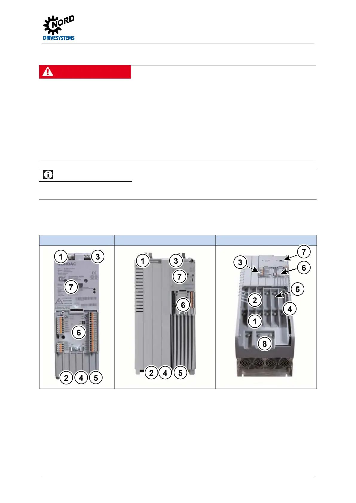
Depending on the size of the frequency inverter, the connection terminals for the supply cables and
the control cables are located in different positions. According to the configuration of the frequency
inverter, various terminals are not present.
Size 1 - 4 Size 5 - 7 Above size 8
Mains connection L1, L2/N, L3, PE X1 Above size 8: X1.1, X1.2
Braking resistor +B, -B X2 Above size 8: X30
Control terminals IOs, GND, 24Vout, IG, DIP for AIN
X4, X5, X6, X7, X14
Above size 8: -DC, CP, PE
 Loading...

