SK 500E – Brief instructions for frequency inverters
18 BU 0540 EN-1516
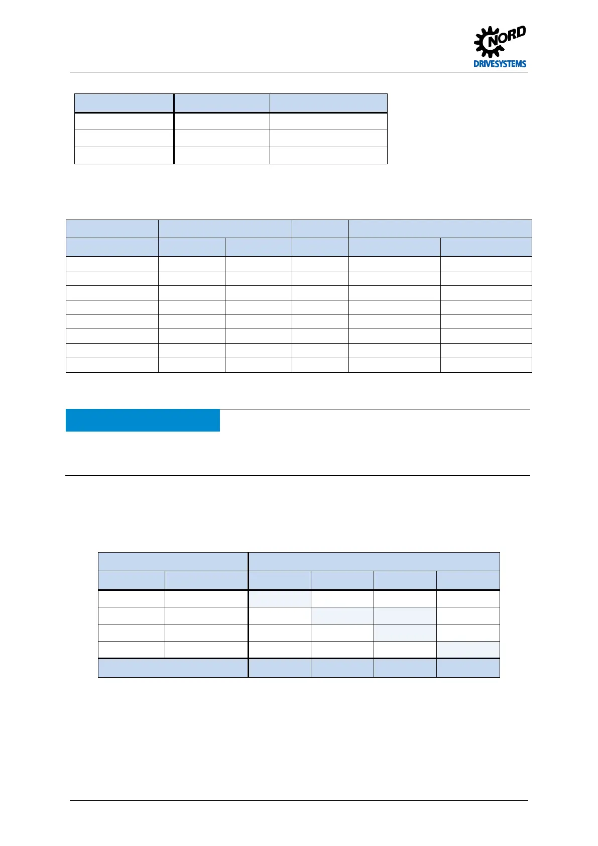
To connect the power unit, the following tools must be used:
Frequency inverter Tools Type
Size 1 - 4 Screwdriver SL / PZ1; SL / PH1
Size 5 - 7 Screwdriver SL / PZ2; SL / PH2
Size 8 - 11 Socket wrench SW 13
Table 5: Tools
Connection data:
Frequency inverter Cable Ø [mm²] AWG Tightening torque
Size rigid flexible [Nm] [lb-in]
7 0.5 … 50 0.5 … 35 20-1 2.5 … 4 22.12 … 35.4
Table 6: Connection data
NOTICE
Brake voltage supply
The voltage supply for an electro-mechanical brake (or its brake rectifier) must be via the mains.
Connection to the output side (connection to the motor terminals) may cause the destruction of the brake or the
frequency inverter.
Pos: 71 /Anlei tunge n/Ele ktro nik/FU und Start er/2. Mont age und Ins tall ation/ Ele ktrisc her Ansc hluss /SK 50 0E/2.1 0.4 Ele ktris cher Ansc hluss L eist ungstei l -Teil 1 - Netz ansc hluss ( X1) [BU 0 500] @ 1\ mod_1331195429990_388.docx @ 17590 @ 5 @ 1
Mains connections (X1 – PE, L1, L2/N, L3)
No special safety measures are required on the mains input side of the frequency inverter. It is
advisable to use the normal mains fuses (see technical data) and a main switch or circuit breaker.
Frequency inverter data Permissible mains data
Voltage Power 1 ~ 115 V 1 ~ 230 V 3 ~ 230 V 3 ~ 400 V
115 VAC 0.25 … 0.75 kW X
230 VAC 0.25 … 2.2 kW X X
230 VAC ≥ 3.0 kW X
400 VAC ≥ 0.37 kW X
Connections
L/N = L1/L2 L/N = L1/L2 L1/L2/L3 L1/L2/L3
Isolation from or connection to the mains must always be carried out for all the poles and
synchronously (L1/L2/L2 or. L1/N).
Pos: 72 /A nl eitu nge n/El ek tro nik/FU u nd S tart er/ 2. M o ntag e un d Ins tall ati on/ El ektri sc her Ansc hluss /SK 50 0E/2.1 0.4 Ele ktris cher An schl uss Leis tungst eil -Teil 1 - N etzans chl uss (X1) A chtung _Bet rieb _IT[BU 0500] @ 11 \mod_1459850218261_388.docx @ 315795 @ @ 1
 Loading...

