2 Assembly and installation
BU 0540 EN-1516 23
Relevance
SK 500E
SK 505E
SK 510E SK 511E
SK 515E
SK 520E SK 530E
SK 535E
√
√
√
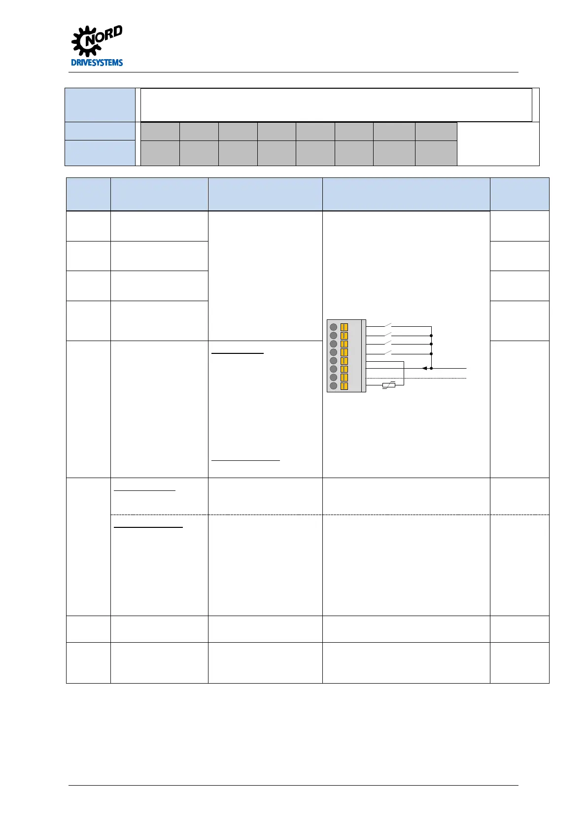
Terminals X5:
21 22 23 24 25 44* 40 41
* Terminal 44:
up to Size 4: VI
Size 5 and above:
VO
DIN1 DIN2 DIN3 DIN4 DIN5 V…24V GND/0V VO 5V
Designation
Terminal Function
[factory setting]
Data Description / wiring suggestion Parameter
21 Digital input 1
[ON right]
7.5...30V, R
i
=6.1kΩ
Not suitable for thermistor
evaluation.
HTL encoders can only be
connected to DIN2 and
DIN4
Limiting frequency:
max. 10 kHz
Each digital input has a reaction time of
≤ 5ms.
21
22
23
24
25
44
40
41
18 … 30V
motor - PTC
GND / 0V
P420
22 Digital input 2
[ON left]
P421
23 Digital input 3
[parameter set bit0]
P422
24 Digital input 4
P429]
P423
25 Digital input 5
[no function]
Only S1 – S4
2.5...30V, R
i
=2.2kΩ
Not suitable for evaluation
of a safety device.
Suitable for thermistor
evaluation with 5V.
NOTE: For the motor
thermistor P424 = 13 must
be set.
Size 5 and above
Thermistor on X13:T1/T2
P424
44 Size 1 to Size 4
VI 24V supply voltage
input
18…30V
min. 800 mA (input)
Voltage supply for the FI control unit. Is
essential for the function of the
frequency inverter.
Size 5 and above
VO 24V supply voltage
output
24V ± 25%
max. 200 mA (output)
short circuit resistant
Supply voltage provided by the
frequency inverter for connection to the
digital inputs or the supply of a 10-30V
encoder.
The 24V control voltage is generated by
the FI, however it can also be supplied
via the terminals X12:44/40 (Size 8 and
above: X15:44/40). Supply via terminal
X5:44 is not possible.
40 Reference potential for
digital signals
0V digital Reference potential
41 5V supply voltage
output
5V ± 20%
max. 250 mA (output)
short-circuit resistant
Voltage supply for motor-PTC
Pos: 83 /A nl eitu nge n/El ek tro nik/FU u nd S tart er/ 2. M ont age und Ins tall ation/ Ele ktrisc her Ansc hluss /SK 50 0E/2.1 0.5 Ele ktris cher An schl uss Ste uertei l- Kle mme nbloc k X 6 – Encoder [SK 500...535E] @ 1\mod_1341401891684_388.docx @ 29313 @ 5 @ 1
 Loading...

