Do you have a question about the Nordyne iQDrive Split System Heat Pump and is the answer not in the manual?
Explains the heat pump system, its components, and compatible equipment for residential use.
Lists additional documentation required for installation and operation of the iQ system.
Guidelines for installing the outdoor unit on a concrete slab for proper drainage and stability.
Recommendations for roof mounting to prevent structural overload and noise transmission.
Details on complying with codes for outdoor unit power wiring, including wire sizing and connection points.
Instructions for connecting 24 VAC control power and communication bus wiring between system components.
Steps for connecting the Airzone control board to the iQ communication bus for zoning systems.
Emphasizes verifying correct routing and secure connections for all power and control wiring.
Guidance on direct routing, insulation, support, and material for refrigerant lines.
Safety precautions and methods for brazing refrigerant line connections using appropriate alloys.
Step-by-step instructions for evacuating the system to remove non-condensables and water vapor.
Methods for charging the system with refrigerant, including preferred weighing and sub-cooling techniques.
Procedures for charging based on subcooling in cooling and heating modes when outdoor temps vary.
Overview of the controller's role in configuration, service tests, and diagnostics, with navigation basics.
Accessing and configuring system parameters like configuration, accessories, and service tests.
Details on defrost, dealer info, heat off delay, altitude adjust, and accessories configuration.
Accessing tests like Charge Mode, Furnace Tests, and Run Tests for diagnostics and operational checks.
Accessing detailed system data like fault status, communication, temperature, and zoning information.
Setting the outdoor temperature below which backup heat engages instead of the heat pump.
Configuring date, time, and program schedule usage for optimal system operation and energy savings.
Setting humidity setpoints and managing the system's dehumidification capabilities.
Configuring smart recovery and managing zone control settings for iQ Zone systems.
A summary of initial steps for operating the heat pump system in cooling, heating, or fan modes.
How zone control is enabled by default and how to manually disable it if needed.
Sequence of tasks for installing hardware, wiring, and performing initial checks before system startup.
Verifying communication links and testing the refrigerant system after charge adjustment.
Reviewing fault logs, confirming system configuration, and checking zone setup for iQ Zone systems.
Diagnosing issues with the controller, inverter, and outdoor interface board using LEDs and fault messages.
Addressing frequent problems like delayed compressor start/stop, fan operation, and unit response to temperature.
Regular checks for filters, condensate lines, outdoor coils, and annual service by a technician.
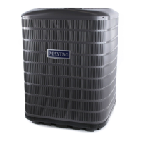
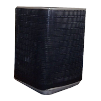
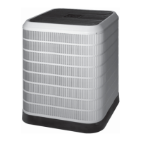
Diagram showing the physical dimensions and clearance requirements for the outdoor unit.
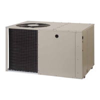
The iQDrive Split System Heat Pump is an integral part of a larger interconnected system designed to provide comprehensive temperature, airflow, and humidity control for residential or similarly sized buildings. This system comprises the outdoor unit, a dedicated iQ controller (thermostat), and an iQ system-compatible indoor unit, which can be either an air handler with electric strip heat or a gas furnace. For proper functionality, all these components must be matched and intended for use within this specific system. Compatible accessory equipment includes humidifiers, electric or electronic air cleaners, and UV sterilizing lamps.
The iQDrive heat pump system is designed to efficiently heat and cool a building while also managing humidity levels. Its core function is to maintain a comfortable indoor environment by controlling the operation of the outdoor unit, indoor unit, and any connected accessories. The system operates based on settings configured through the iQ controller, which acts as the central interface for users and installers.
In cooling mode, the heat pump functions as an air conditioner, removing heat from the indoor space and expelling it outdoors. In heating mode, it extracts heat from the outdoor air and transfers it indoors. When outdoor temperatures are too low for efficient heat pump operation, the system can automatically switch to auxiliary heat (electric strip heat or gas furnace) to meet the heating demand. The iQ controller allows for precise control over these operations, including setting desired temperatures, fan speeds, and humidity levels.
The system also incorporates advanced features such as demand defrost, which triggers a defrost cycle when the outdoor coil temperature drops below a certain threshold, or after a maximum operating time, to prevent frost buildup and maintain heating efficiency. The controller provides detailed information about system status, including fault conditions, temperatures, and communication data, which is crucial for diagnosis and troubleshooting.
The iQDrive system offers a user-friendly interface through its iQ controller, enabling both homeowners and installers to manage its various functions.
The Main Screen of the iQ controller prominently displays room temperature and the current operating mode (e.g., COOL or HEAT). Users can navigate through menus using arrow keys to access different settings. For iQ Zone systems, the Main Screen also shows "ZONE CNTL" under the operating mode.
Installers use a dedicated "INSTALLER SETTINGS" menu for initial system configuration and setup. This includes:
These screens provide detailed operational data and diagnostic information:
Regular maintenance is crucial for optimal system performance and longevity.
The iQDrive system is designed for comprehensive climate control, with detailed configuration and diagnostic capabilities accessible through its iQ controller, making it a versatile and efficient solution for modern buildings.
| Refrigerant | R-410A |
|---|---|
| Stages | Variable Speed |
| SEER Rating | Up to 20 |
| HSPF Rating | Up to 10 |
| Cooling Capacity (BTU/h) | 18, 000 - 60, 000 |
| Heating Capacity (BTU/h) | 18, 000 - 60, 000 |
| Efficiency | Up to 20 SEER |
| Compressor | Inverter-Driven |
| Warranty | 10-Year Limited Warranty |