Do you have a question about the Nordyne Q5RD Series and is the answer not in the manual?
Details on how to operate the heat pump in cooling mode.
Details on how to operate the heat pump in heating mode.
Information on using auxiliary electric heat when heat pump is unavailable.
Explanation of the heat pump's automatic defrost cycle.
Procedure for safely shutting down the heat pump system.
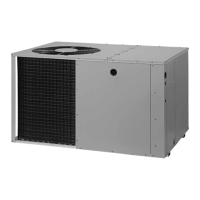
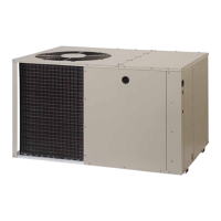
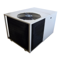
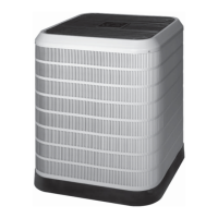
Overview of the single packaged heat pump's assembly and installation requirements.
Key checks and considerations before commencing unit installation.
Guidance on selecting the optimal placement for the outdoor unit.
Required spacing around the unit for proper airflow and servicing.
Guidelines for designing and installing the air duct system.
Procedures for unpacking and initial installation of the unit.
Instructions for attaching supply and return air collars and flexible ducts.
Guidance on locating and installing the return air box.
Steps for locating and installing the supply air damper.
Instructions for installing the condensate drain and trap.
Pre-checks for electrical supply and wiring integrity.
Specifications and recommendations for unit power supply.
Guidance on selecting and installing fuses or breakers.
Instructions for changing blower speed for optimal performance.
Explanation of how the defrost cycle is managed.
Information on installing optional auxiliary electric heat kits.
Essential safety instructions for unit grounding.
Pre-checks and steps for initiating unit operation.
Procedures to verify heating, cooling, and air circulation.
Details on the time-delay feature protecting the compressor.
Methods for testing the unit's defrost cycle functionality.
Explanation of safety switches protecting the compressor.
Routine service tasks for optimal performance and longevity.
Diagram and measurements for the Q5RD unit.
Table listing physical specifications for Q5RD models.
Cooling mode refrigerant charge data for 2-ton Q5RD models.
Cooling mode refrigerant charge data for 2.5-ton Q5RD models.
Cooling mode refrigerant charge data for 3-ton Q5RD models.
Cooling mode refrigerant charge data for 3.5-ton Q5RD models.
Cooling mode refrigerant charge data for 4-ton Q5RD models.
Cooling mode refrigerant charge data for 5-ton Q5RD models.
Heating mode refrigerant charge data for 2-ton Q5RD models.
Heating mode refrigerant charge data for 2.5-ton Q5RD models.
Heating mode refrigerant charge data for 3-ton Q5RD models.
Heating mode refrigerant charge data for 3.5-ton Q5RD models.
Heating mode refrigerant charge data for 4-ton Q5RD models.
Heating mode refrigerant charge data for 5-ton Q5RD models.
Schematic for wiring the 2 and 2.5 ton Q5RD/PPH2RD series units.
Schematic for wiring the 3, 4, and 5 ton Q5RD/PPH2RD series units.
Diagrams illustrating thermostat wiring for different configurations.
This document serves as both a user's manual and installation instructions for a Q5RD Series 13 SEER Single Package Heat Pump, designed for single-stage operation with R-410A refrigerant. It emphasizes the importance of reading the information thoroughly to become familiar with the appliance's capabilities and use before operation or maintenance. The manual is primarily intended for qualified individuals experienced in the proper installation of such appliances, noting that some local codes may require licensed personnel.
The Q5RD Series heat pump is an all-weather comfort-control appliance designed to both heat and cool a home year-round, offering energy-saving comfort. It operates on the principle that heat is always present in the air, even at temperatures below freezing. During colder months, the heat pump absorbs available heat energy from the outdoors and transfers it inside the home. This efficient process means the user pays for "moving" heat rather than generating it, unlike traditional furnace designs. For example, at 47°F (8°C), the heat pump can deliver approximately 3.5 units of heat energy for each unit of electrical energy consumed, compared to a maximum of 1 unit from conventional heating systems. In warmer temperatures, the heat pump reverses the flow of the heat-absorbing refrigerant, functioning as an energy-efficient central air conditioner by absorbing excess heat from inside the home and exhausting it outdoors.
The unit features a Demand Defrost system that monitors ambient and coil temperatures to regulate the defrost function. During a defrost cycle, both the outdoor condenser fan and compressor turn off initially. After about 30 seconds, the compressor turns on to heat the outdoor coil, melting any snow and ice. Steam may rise from the outdoor unit during this process. Once defrost is complete, the outdoor fan motor restarts, and the compressor turns off briefly before restarting normal operation after approximately 30 seconds.
The control circuit includes an anti-short cycle timer, which prevents the compressor from restarting within 5 minutes of its last operation or a power interruption, protecting the equipment.
Operating the heat pump involves setting the thermostat's system mode and temperature. For cooling, the system mode should be set to COOL or AUTO, and the fan mode to AUTO. The temperature selector is then set to the desired level, causing the outdoor fan, compressor, and blower motor to cycle on and off to maintain the indoor temperature. For heating, the system mode should be set to HEAT or AUTO, and the fan mode to AUTO. The temperature selector is adjusted to the desired heating level, and the compressor, outdoor fan, and blower motor will cycle to maintain the indoor temperature.
If the temperature or system mode is readjusted, the outdoor unit's fan and compressor may not start immediately due to the protective timer circuit. Some thermostats may include an "EM HT" or "AUX HT" mode for emergency heating. This mode should only be used if a problem is suspected, as it locks off the compressor and outdoor fan, relying on supplemental electric resistance heating (if installed), which increases electric utility costs. To shut down the system, the thermostat's system mode should be set to OFF and the fan mode to AUTO.
The thermostat also features an ON-AUTO fan switch, allowing the homeowner to operate the indoor blower for air circulation even when heating or cooling is not active. The thermostat should be mounted about 5 feet above the floor on an inside wall, avoiding outside walls or areas subject to radiant or convective heat sources.
Proper maintenance is crucial for optimal performance of the heat pump. This equipment requires certain mechanical skills and tools for maintenance; if these skills are not possessed, the user should contact their dealer for service or maintenance contracts. Routine maintenance includes several key tasks:
The manual also provides detailed instructions for blower speed adjustment, noting that the factory speed setting may need to be changed for optimum system performance and comfort. This involves disconnecting electrical power, removing the service panel, verifying the required speed from airflow data, and placing the appropriate wire on the motor speed tap. All factory wiring should be checked for loose connections.
| Sound Rating | 74 dB |
|---|---|
| Refrigerant | R-410A |
| Voltage | 208/230V |
| Phase | 1 |
| Cooling Capacity | 60, 000 BTU/h |