20
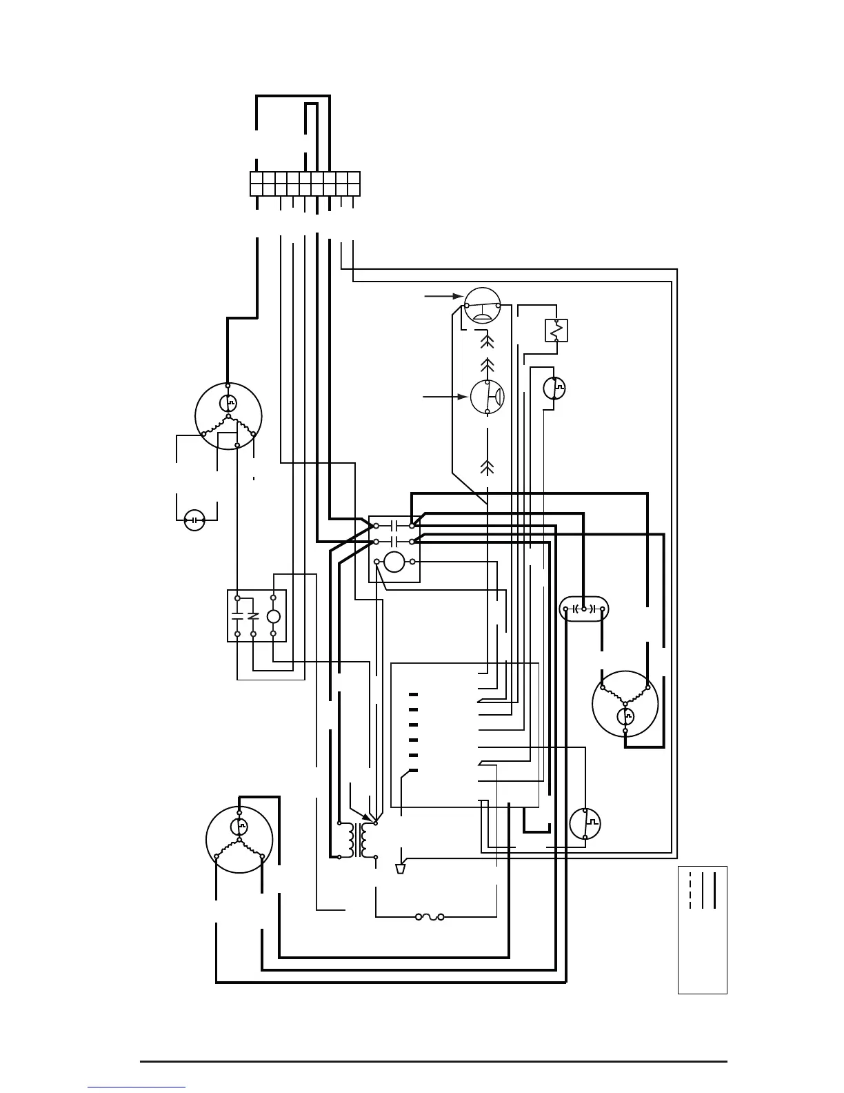
Figure 10. Q5RD / PPH2RD Series Wiring Diagram - 2 & 2.5 Ton Units
WIRING DIAGRAMS
OUTDOOR FAN
MOTOR
4
3
2
1
8
7
6
5
9
4
3
2
1
8
7
6
5
9
TO “G” ON
T- S TAT
3 AMP
FUSE
BLOWER
RELAY
BLOWER
MOTOR
CAPACITOR
REVERSING
VALVE
COIL
DEFROST
SENSOR
DUAL
CAPACITOR
COMPRESSOR
TRANSFORMER
240V
24V
COM
ROUTE WIRE INTO
ELEC. BOX ON UNIT.
TIE EXTRA MATERIAL
UP SO IT IS OUT OF THE
WAY.
REF; 631849 AMP
ADAPTER
Y
C
OW2RE
DEFROST
CONTROL
BOARD
DFTE R W2 O Y C
T2
T1
DF1
DF2
C
H
C
F
R
S
NO
S
R
C
NC
COM
T1
T2
L2
L1
OUTDOOR THERMOSTAT
(ON SELECT MODELS
BROWN JUMPER
IS INSTALLED)
RED
HIGH
PRESSURE
SWITCH
LOW
PRESSURE
SWITCH
(SELECT MODELS ONLY)
BLUE
BLUE
RED
RED
RED
RED
RED
ORANGE
YELLOW
WHITE
WHITE
WHITEWHITE
GREY
BROWN
BLACK
BLACK
GREEN
BROWN
ORANGE
BLUE
BLACK
BROWN
BROWN
RED
RED
RED
BLACK
BLACK
YELLOW
BLACK
YE
YE
YE
YE
YELLOW
GREY
BLACK
BLACK
VIOLET
BLACK
FIELD WIRING
LEGEND:
LOW VOLTAGE
HIGH VOLTAGE
NOTES:
208/230 VOLT
SMALL PACKAGE HEAT PUMP
60HZ/SINGLE PHASE
1. Disconnect all power before servicing.
2. For supply connections use copper conductors only.
3. Not sutiable on systems that exceed 150V to ground.
4. For replacement wires use conductors suitable for 105°C.
1. Couper le courant avant de faire letretine.
2. Employez uniquement des conducteurs
en cuiver.
3. Ne convient pas aux installations de plus
de 150V a la terre.
7108380
 Loading...