EasyManua.ls Logo

Nordyne T4BD-042 Series User Manual

Nordyne T4BD-042 Series
20 pages
To Next Page IconTo Next Page
Page #1 background imageLoading...
Page #1 background image
13 SEERSPLIT SYSTEM HEAT PUMP WITH MICROCHANNEL COILS
T4BD - 042, 048, & 060 (3.5, 4, & 5 TON) SERIES
SINGLE PHASE MODELS
REFRIGERANT CHARGING ............................... 9
Charging the Unit in AC mode ..................................... 9
Charging Charts & Application Notes - (Cooling Only)
10
Figure 6. Charging Chart for 3.5 Ton Units
(TXV Matches)
...........................................10
Figure 7. Charging Chart for 4 Ton Units
(TXV Matches)
........................................... 11
Figure 8. Charging Chart for 5 Ton Units
(TXV Matches)
........................................... 11
Charging Tables & Application Notes - (Cooling Only)
12
Table 5. Charging Table for T4BE-042KA Series
(3.5 Ton Models) – Restrictor Matches
....... 12
Table 6. Charging Table for T4BE-048KA Series
(4 Ton Models) – Restrictor Matches
..........12
Table 7. Charging Table for T4BE-060KA Series
(5 Ton Models) – Restrictor Matches
..........13
Heat Mode Tables & Application Notes (Heating Only)
. 14
Table 8. Heat Mode Table for 3.5 Ton Models
..........15
Table 9. Heat Mode Table for 4 Ton Models
.............15
Table 10. Heat Mode Table for 5 Ton Models
...........15
WIRING DIAGRAMS ............................................ 16
Figure 9. Wiring Diagram for 3.5 - 5 Ton Models
Equipped With CoreSense
TM
Diagnostic
Module
........................................................16
Figure 10. Wiring Diagram for 3.5 - 5 Ton Models
NOT Equipped With CoreSense
TM
Diagnostic Module ....................................17
Figure 11. Wiring Diagram for 3.5 - 5 Ton Models
Equipped with Low Pressure Switch
........18
INSTALLATION / PERFORMANCE CHECKLIST 20
IMPORTANT
It is your responsibility to know this product better than your customer. This includes being able to install the product
according to strict safety guidelines and instructing the customer on how to operate and maintain the equipment for
the life of the product. Safety should always be the deciding factor when installing this product and using common
sense plays an important role as well. Pay attention to all safety warnings and any other special notes highlighted
in the manual. Improper installation of the furnace or failure to follow safety warnings could result in serious injury,
death, or property damage.
These instructions are primarily intended to assist qualified individuals experienced in the proper installation of
this appliance. Some local codes require licensed installation/service personnel for this type of equipment. Please
read all instructions carefully before starting the installation. Return these instructions to the customer’s package
for future reference.
DO NOT DESTROY. PLEASE READ CAREFULLY & KEEP IN A SAFE PLACE FOR FUTURE REFERENCE.
INSTALLATION INSTRUCTIONS
IMPORTANT SAFETY INFORMATION ............... 2
HEAT PUMP INSTALLATION .............................. 3
General Information ..................................................... 3
Before You Install the Heat Pump
................................3
Locating the Heat Pump
..............................................3
Packaging Removal
.....................................................3
Ground Level
...............................................................3
Rooftop
........................................................................3
Connecting Refrigerant Tubing Between the Indoor
& Outdoor Unit
............................................................. 4
Outdoor Orifice Removal & Installation
........................4
ELECTRICAL WIRING ......................................... 5
Pre-Electrical Checklist ................................................5
Line Voltage
.................................................................5
Grounding
.................................................................... 6
Thermostat / Low Voltage Connections
.......................6
CoreSense
TM
Diagnostics Module................................6
Compressor Protection
..............................................7
Resetting Alert Codes
................................................7
START UP & ADJUSTMENTS ............................ 7
Pre-Start Check List .....................................................7
Start-Up Procedures
.................................................... 7
Air Circulation - Indoor Blower
.....................................7
Short Cycle Protection
................................................. 7
System Cooling
............................................................8
System Heating
............................................................8
Defrost Control Board Test Pins
.................................. 8
HEAT PUMP MAINTENANCE ............................. 9
Question and Answer IconNeed help?

Do you have a question about the Nordyne T4BD-042 Series and is the answer not in the manual?

Nordyne T4BD-042 Series Specifications

General IconGeneral
BrandNordyne
ModelT4BD-042 Series
CategoryHeat Pump
LanguageEnglish

Summary

Important Safety Information

Electrical Shock, Fire, and Explosion Hazards

Details risks associated with electrical hazards and improper servicing.

Refrigerant Handling and System Pressure Warnings

Emphasizes proper handling of R410A and system pressure safety.

Heat Pump Installation

General Installation Guidelines

Covers unit purpose, performance, and basic installation requirements.

Outdoor Unit Location and Clearances

Discusses optimal placement and required clearances for the outdoor unit.

Refrigerant Tubing and Orifice Installation

Guides on connecting refrigerant tubing and adjusting the outdoor unit's orifice.

Electrical Wiring

Pre-Electrical Checklist

Steps to verify voltage, supply, and wiring before electrical connection.

Line Voltage Wiring and Connections

Details on connecting outdoor unit power supply, disconnects, and wire sizing.

Grounding and Thermostat Connections

Specifies grounding requirements and low voltage thermostat connections.

CoreSense Diagnostics Module

Information on the CoreSense module for system diagnostics and troubleshooting.

Start Up and Adjustments

Pre-Start Checklist and Procedures

Steps to perform before starting the unit, including checks and procedures.

System Cooling Operation

Verifies correct operation of the unit in cooling mode.

System Heating Operation

Verifies correct operation of the unit in heating mode.

Defrost Control Board Test Pins

Procedures for testing the defrost control board functionality.

Heat Pump Maintenance

Routine Maintenance Procedures

Outlines essential maintenance tasks for optimal heat pump performance.

Lubrication Considerations

States that the compressor is hermetically sealed and requires no lubrication.

Refrigerant Charging

Charging the Unit in AC Mode

Detailed steps for charging the unit in AC cooling mode.

Cooling Mode Charging Charts

Provides charts and application notes for cooling mode refrigerant charging.

Heating Mode Charging Tables

Presents tables and notes for refrigerant charging in heating mode.

Wiring Diagrams

Wiring Diagram with CoreSense Diagnostics Module

Illustrates electrical connections for units equipped with CoreSense.

Wiring Diagram without CoreSense Module

Shows electrical connections for units not equipped with CoreSense.

Wiring Diagram with Low Pressure Switch

Depicts electrical wiring for units featuring a low pressure switch.

Installation and Performance Checklist

Electrical System Performance Checks

Verifies the integrity and correctness of the electrical system installation.

Refrigeration System Performance Checks

Checks critical refrigerant system parameters after installation.

Replacement Parts Information

Lists available replacement parts and provides ordering information.
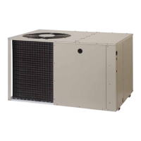
Related product manuals