Do you have a question about the Nordyne CSH4BE and is the answer not in the manual?
Covers cleaning filters, clearing outdoor unit debris, and checking for obstructions.
Highlights system pressures and safe handling of refrigerant and equipment.
Emphasizes following instructions on labels, tags, and precautions.
Details safety requirements and equipment for brazing operations.
Steps for unpacking equipment and inspecting for damage.
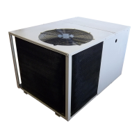
Guidelines for choosing an optimal location for the outdoor unit.
Critical safety warning to turn off power before wiring.
Compliance with NEC and local codes for electrical power wiring.
Ensuring air filters are clean and thermostat is set correctly before startup.
Procedures for safely applying power and inspecting wiring.
Steps to verify system operation, including indoor blower and safety switches.
Guides on understanding the meaning of LED flashes for troubleshooting.
Troubleshooting common wiring errors for the diagnostic module.
Detailed interpretation of LED status and corresponding troubleshooting actions.
Critical safety warning regarding refrigerant handling by qualified personnel.
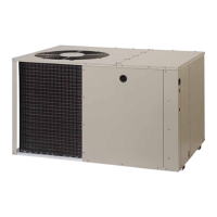
This document provides user and installation instructions for a 14 SEER R-410A High Efficiency Split System Outdoor Heat Pump. It is designed for use with various indoor heating and cooling appliances, including fossil fuel furnaces, electric furnaces, air handlers, and evaporator coils. The instructions are primarily for qualified individuals experienced in HVAC installation and service, with a note that local codes may require licensed personnel. Homeowners are advised against attempting installation or service themselves.
The heat pump operates on a principle that allows it to both heat and cool a home by transferring heat.
The heat pump system is controlled via a thermostat, which allows users to set desired temperatures and operating modes.
The thermostat includes an "EM. HT." setting for backup heating. This mode should only be used if there's a suspected problem with the outdoor unit. When activated, the outdoor unit is locked off, and supplemental heat (typically electric resistance heating) is used. Sustained use of emergency heat will increase electricity costs.
During cold weather heating, the outdoor unit's heat transfer coil may accumulate snow and ice. This is normal, and the unit will periodically defrost itself. During defrost, the outdoor fan stops, the compressor continues to run, heating the outdoor coil to melt the ice. Steam may rise from the unit as melted frost evaporates. The defrost cycle timer, located on the defrost control board, can be set to 30, 60, or 90-minute intervals, with 30 minutes being the factory default. Setting it to 90 minutes can maximize heating performance.
Set the thermostat system switch to "OFF" and the fan switch to "AUTO." The system will then cease operation.
Set the thermostat fan switch to "ON." The indoor blower will run continuously, regardless of the system switch setting (including "OFF"), until the fan switch is reset to "AUTO." This feature is useful for circulating indoor air to equalize temperature imbalances caused by factors like sun load, cooking, or fireplaces.
This component prevents electrical auxiliary heat from operating above a desired set point, which is determined by the building's design heat load. It is adjustable from 0°F to 45°F, with a factory setting of 40°F.
This module assists in troubleshooting heat pump and air conditioning system failures, particularly for single-phase systems with scroll compressors that have internal overload protection. It monitors compressor and thermostat demand data to detect electrical and system-related failures without additional sensors. A flashing LED indicator communicates an ALERT code, guiding service technicians to the root cause of a problem. Note: This module is a monitoring device and does not provide safety protection or control other devices.
Regular maintenance is crucial for the heat pump's efficient and reliable operation.
| SEER | Up to 14 |
|---|---|
| Voltage | 208/230V |
| Phase | 1 |
| Refrigerant | R-410A |
| Cooling Capacity | 48000 BTU/h |
| Tonnage | 4 Ton |