10
MTG. PLATE TABS
SLIDE FURNACE
ALL THE WAY BACK
ONTO MTG. PLATE
SUPPLY AIR DUCT
Knockout Over Holes
SECURE FURNACE
WITH 2 FASTENERS AT FRONT
CORNER HOLES
SUPPLY AIR DUCT
FUEL
LINE
HOLES
MTG. PLATE TABS
SLIDE FURNACE
ALL THE WAY BACK
ONTO MTG. PLATE
SECURE FURNACE
WITH 2 FASTENERS
AT FRONT CORNER HOLES
Duct
Duct Connector
Narrow Duct
Staple Folded Duct
Flap (typ) to side of Duct
Connector
Duct
STEP 4.
STEP 1.
"A" "A"
"B"
"B"
Cut- Out
Area"A"
Cut- Out
Area "A"
Fold Back Flap "B"
Fold Back Flap "B"
Top of Duct
"A" "A"
STEP 2.
"B"
"B"
Fold Back Flap"B"
Cut
Lines Duct
Fold Back Flap"B"
STEP 3.
Bend Duct Connector Tabs Up
and Over- (along length of duct)
Duct
Flap "B"
Duct
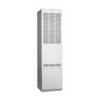
Figure 17.
Figure 18.
1. Score and cut the top of the metal duct as indicated in Step
1 or Step 2. With Step 1 choice, also cut out the metal from
the shaded area “A”.
2. Fold the duct flap “B” up, (See Step 3).
3. At the front-to-back of duct run (Area “A”), bend the duct
tabs and secure them directly to the duct.
4. At Area “B”, bend the duct tabs up and back over, around
the duct connector, (See Step 3).
5. Fold/form the duct flap against the side of the duct
connector and attach as shown, (See Step 4). Use three
(3) staples (minimum) on each duct flap OR, if a 2X block/
joist is not provided, use two (2) sheet metal screws
(minimum) on each duct flap. An alternate attachment
method is acceptable, as long as the plenum is securely
attached.
6. Tape the duct flap edges with an approved tape for a leak-
free joint.
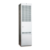
INSTALL FURNACE
a. Remove furnace outer door(s) and bottom fuel line
knockout.
b. Place furnace onto duct connector and center with
floor opening.
c. Slide onto mounting plate. (Bottom rear slots on
furnace should engage with mounting plate tabs.)
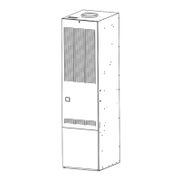
d. Secure front with one (1) fastener at each corner (See
Figure 19 or 20).
NOTE: Additional fasteners may be used at rear, sides or
through door frame, as desired, to secure furnace to closet or
alcove framing.
INSTALL ROOF JACK
Apply caulking compound on underside of roof flashing to
form a continuous strip at least 3/8" wide (see Figure 21)
around the underside of the perimeter of the flashing. Connect
Roof Jack Assembly to the furnace. Insert telescoping Roof
Jack Assembly through the opening cut on the roof. Connect
flue pipe to flue collar of furnace. Connect combustion air pipe
to furnace collar with sheet metal screw (See Figure 22). It is
recommended that the connection of the combustion air pipe
to the furnace be made before the flashing is secured to the
roof to maintain alignment of roof jack and furnace connections.
NOTE: For replacement furnaces, be sure the inner flue pipe
connects over the furnace vent collar. DO NOT use a smaller
diameter inner flue pipe which could slide inside the
furnace vent collar and restrict the flow of furnace flue
products.
Attach Roof Flashing: If necessary, shift roof flashing slightly
in the roof opening so that assembly is in good alignment with
furnace. Press down firmly over caulking on roof flashing to
make the seal with roof water tight. Secure flashing with
appropriate fasteners. As an added protection against leaks,
coat the flashing plate and fasteners with approved roofing
compound.
If flashing mounted on 12 degree angle is used it may be
necessary to adjust the angle to match the roof pitch; (1/12 -
4/12 maximum).
Figure 19. “A” & “B” Cabinet Furnaces
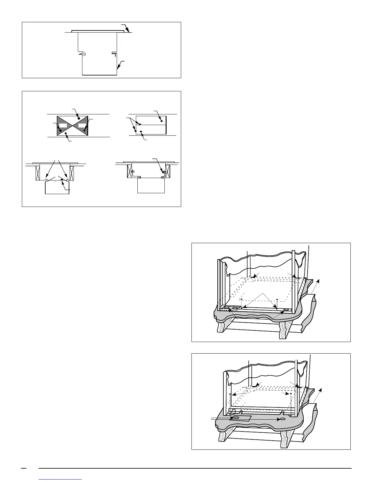
Figure 20. “A” Cabinet Furnace on 911969 Coil Cabinet
 Loading...