3
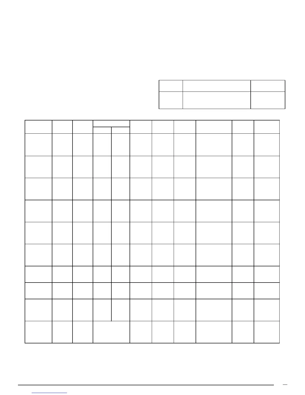
Table 2. M1 Furnace Specifications
NOTICE TO INSTALLER
Installer is advised to follow carefully all instructions and
warnings in this manual to insure maximum performance,
safety, and operating efficiency of these appliances. Improper
installation may create hazardous conditions, and will void
the appliance warranty.
1. SPECIFICATIONS
GENERAL DESCRIPTION
M1 Series gas and oil furnaces are listed direct vent (sealed
combustion), downflow heating appliances for manufactured
(mobile) homes, recreational vehicles, and for use in residential/
modular/commercial construction. The furnace must be located
so that venting can be properly achieved.
“A” cabinet models may be installed with Optional Coil Cabinet
Model #911969 for air conditioning.
“B” cabinet models are factory equipped with a built-in coil cavity.
Multi-speed blower assemblies as shown in Table 3 have
been certified for field installation in M1 Series furnaces. An air
conditioner can be easily field installed with M1GH Series
furnaces if used in conjunction with certified 2-wire relay box,
p/n 903092A or 4/5 wire relay box 902898A.
Electrical Supply - 120 volts, 60HZ, 1 Ph. Thermostat Circuit - 24 volts, 60HZ, 30 vac
Fuse or Breaker - 15 amps Normal Anticipator Setting - 0.4
Temperature Rise - 45° to 75°F Manifold Pressure - Natural Gas: 3.5” w.c. LP Gas: 10” w.c.
High Altitude - See Table 11. For Canadian High Altitude (2,000’ to 4,500’), reduce the gas manifold pressure
to 3.0” W.C. for natural gas and to 8” W.C. for LP gas.
*Blower capacity only - needs relay box for AC
Table 3. Field Installation Blower Assemblies
A/C Capacity
Blower Wheel Motor-Hp Ton
903412 10 x 8 1/3 2, 2½ & 3
903413 11 x 8 1/2 2, 2½, 3 & 4
903414 10 x 8 3/4 2, 2½, 3, 4 & 5
Part No.
Blower / Motor Assembly
Furnace Input Output Orifice No E.S.P. Pilot Ignitor Comb. Motor A/C Ready
Model No MBtu/h MBtu/h Nat. LP In WC Burner Direct Blower Hp Tons
M1GH 056 56 45 29 45 0.2 x 1/8 2*
M1GB 056 56 45 29 45 0.3 x 1/3 3
M1GC 056 56 45 29 45 0.3 x 1/2 4
M1GD 056 56 45 29 45 0.3 x 3/4 5
M1GH 070 70 57 24 42 0.3 x 1/5 2½*
M1GB 070 70 57 24 42 0.3 x 1/3 3
M1GC 070 70 57 24 42 0.3 x 1/2 4
M1GD 070 70 57 24 42 0.3 x 3/4 5
M1GH 077 77 60 21 40 0.3 x x 1/4 3*
M1GB 077 77 60 21 40 0.3 x x 1/4 3
M1GC 077 77 60 21 40 0.3 x x 1/2 4
M1GD 077 77 60 21 40 0.3 x x 3/4 5
M1GH 090 90 70 17 36 0.3 x x 1/4 3*
M1GB 090 90 70 17 36 0.3 x x 1/4 3
M1GC 090 90 70 17 36 0.3 x x 1/2 4
M1GD 090 90 70 17 36 0.3 x x 3/4 5
M1MA 056 56 46 29 45 0.2 x x 1/8 2
M1MB 056 56 46 29 45 0.3 x x 1/3 3
M1MC 056 56 46 29 45 0.3 x x 1/2 4
M1MD 056 56 46 29 45 0.3 x x 3/4 5
M1MA 070 70 57 24 42 0.3 x x 1/5 2½
M1MB 070 70 57 24 42 0.3 x x 1/3 3
M1MC 070 70 57 24 42 0.3 x x 1/2 4
M1MD 070 70 57 24 42 0.3 x x 3/4 5
M1MB 077 77 62 21 40 0.3 x x 1/4 3
M1MC 077 77 62 21 40 0.3 x x 1/2 4
M1MD 077 77 62 21 40 0.3 x x 3/4 5
M1MB 090 90 72 17 36 0.3 x x 1/4 3
M1MC 090 90 72 17 36 0.3 x x 1/2 4
M1MD 090 90 72 17 36 0.3 x x 3/4 5
M1BA 066 66 53 26 43 0.24 x x 1/5 2½
M1BC 066 66 53 26 43 0.3 x x 1/2 4
M1BB 086 86 68 18 37 0.3 x x 1/4 3
M1BC 086 86 68 18 37 0.3 x x 1/2 4
M1SA 066 66 54
.50 Gph
0.24 x Burner Model 1/5 2½
M1SC 066 66 54
.50 Gph
0.3 x AF-10 Nozzle 1/2 4
M1SB 086 86 71
.65 Gph
0.3 x Spray Angle 1/4 3
M1SC 086 86 71
.65 Gph
0.3 x 80° A 1/2 4
 Loading...