7
APPLICATION NOTES:
a. FAW, FAWT, SAW and SAWT Series Roof Jacks with
a 5" diameter inner vent pipe may be used with all
models of M1 Series gas and oil furnaces.
b. F=Flat Flashing; flexes from 0/12 to 1/12 roof slope.
c. S=Slant Flashing. 2.5/12 Slope flexes from 1/12 to
4/12 roof slope, 4/12 flexes from 3/12 to 5/12.
d. Stainless steel roof jacks are available.
e. If the roof jack crown is covered or blocked with snow,
the furnace will not operate properly. If the home is
located in regions where snow accumulation exceeds
7” (HUD snowload zones) use an external roof jack
extension p/n 901937.
f. M1 furnaces may be used with roof jacks as tall as 170”
(except M1M 056 & M1B 066 models, which are
limited to 120”). An internal roof jack extension (p/n
901935 - 10”, p/n 903107 - 18”) can be used to
increase roof jack height. All connections inside the
home must be made below the ceiling.
These extensions are available as optional accessories and
may be purchased through your NORDYNE distributor.
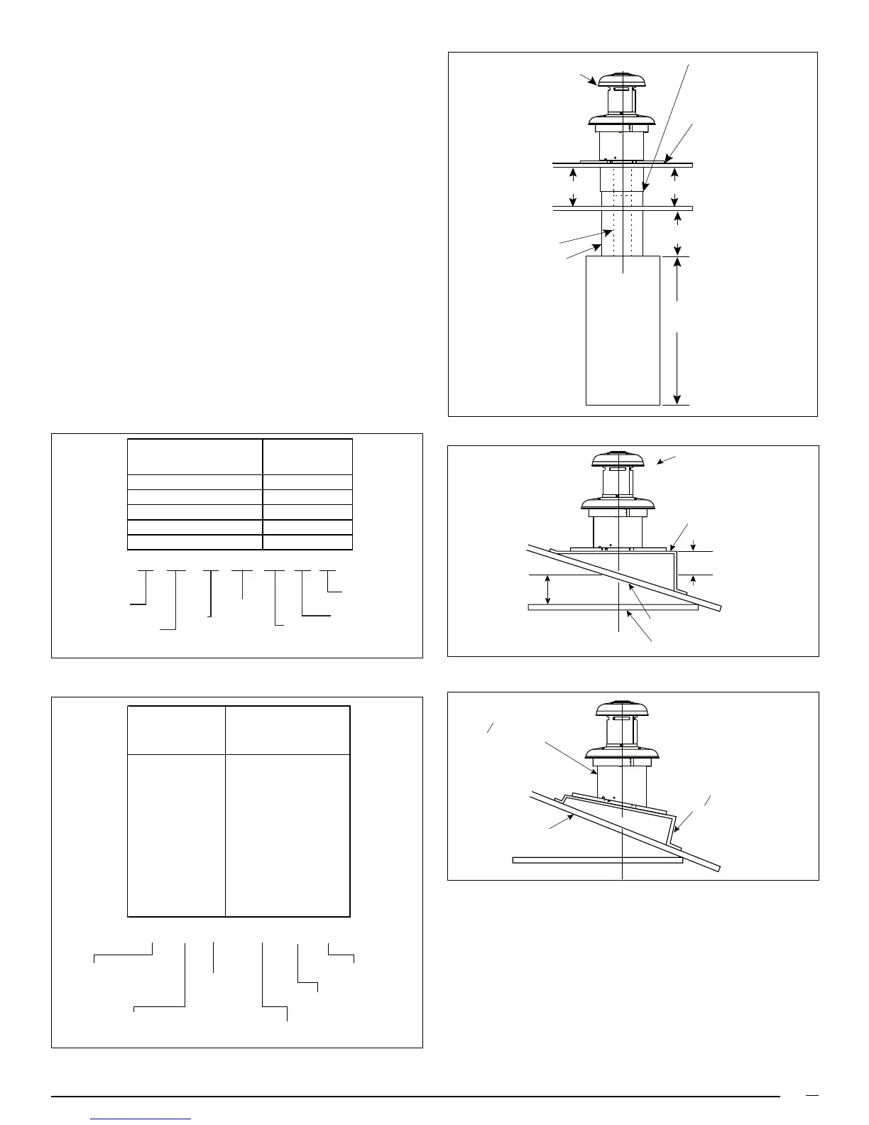
Figure 6. Roof Jack Assemblies
Figure 7.
Figure 8.
Roof Jack
Flat Roof
Ceiling Cavity
Ceiling
Flue Pipe
Combustion
Air Pipe
Flashing
This joint
may be
above ceiling
"A"
"B"
56" or 76"
Furnace
5/12 ROOF SLOPE
2
SLANT DECK
/12
1
2
ROOF JACK WITH
2
FLASHING
/12 SLANT
1
2
SSAW
T
20
32 - 2
AW= ALL WEATHER
FLASHING
PITCH/12" RISE
0=FLAT
2=2.5/12
4=4/12
MIN. ADJ.
LENGTH
F=
S=
FLAT FLASHING
SLANT FLASHING
TYPE:
BLANK=NON-TRANSIT
T= TRANSIT MODE
MAX. ADJ.
LENGTH
FLUE STEEL TYPE
A= ALUMINIZED
S=STAINLESS
S O T 27 45 -5
S= SLAT FLASHING
F= FLAT FLASHING
O= TYPE; STANDARD
H= HIGH WIND
A= ARCTIC ROOF JACK
T= TRANSIT
MODE
TYPE
MIN. ADJ.
LENGTH
MAX. ADJ.
LENGTH
5 = 5" FLUE DIA.
Table 5b. Roof Jack Assemblies
MODEL APPROX. ADJ.
NUMBER LENGTHS*
BELOW FLASHING
FO1323 -5 13" - 23"
FO2343 -5 23" - 43"
SO1835 -5 18" - 35"
SO2447 -5 24" - 47"
SO3263 -5 32" -63"
SO4895 -5 48" - 95"
SOT2442 -5 24" - 42"
SOT2745 -5 27" - 45"
SOT4581 -5 45" - 81"
FOT2846 -5 28" - 46"
10. DUCT CONNECTOR SELECTION
a. Determine depth of floor cavity from surface of floor to
top of supply air duct (See Figure 9).
b. Select appropriate model from Table 7 which matches
X-dimension of the floor cavity. To maximize air delivery,
remove reducer “C” (see Figure 11) to obtain the
largest open area that will fit the duct/floor construction.
Figure 5a. All Weather Roof Jack Assemblies
ROOF JACK
SLANT DECK
FLASHING
PITCHED
ROOF
CEILING
CEILING CAVITY
ROOF OPENING
CEILING OPENING
"X" (SEE TABLE 1)
6
Approx. Length
Model Number Below Flashing
(F,S)AW(T)1523-(0,2,4)(A,S) 15" - 23"
(F,S)AW(T)2135-(0,2,4)(A,S) 21" - 35"
(F,S)AW(T)2747-(0,2,4)(A,S) 27" - 47"
(F,S)AW(T)3563-(0,2,4)(A,S) 35" - 63"
(F,S)AW(T)5195-(0,2,4)(A,S) 51" - 95"
 Loading...