9
13). Installation procedures are suggested for
typical furnace installations and need not be
followed in the exact listed sequence.
CUT OUT FLOOR OPENING & FUEL LINE
HOLE
a. Determine center of closet or alcove (Figure
13).
b. Locate center of the fl oor opening, measured
10” from the rear wall, and mark cut-out
measuring approximately 14-1/2” by 14-1/2”
(± 1”) for model duct connector used (refer
to Figures 10 & 11).
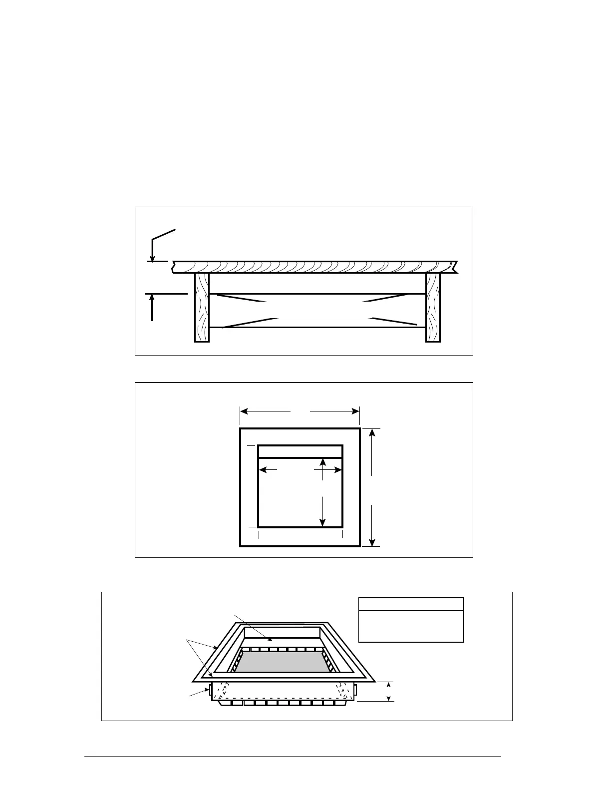
Figure 10.
Figure 9.
Top View
of
Finger Tab
Duct
Connector
x
SUPPLY AIR DUCT
FLOOR CAVITY
(depth equal to "X" in Figure 11 and Table 7)
Figure 11.
X
SEE
TABLE 7
REDUCER
*FELT-SEAL
SPACERS
C
*OPENING TO DUCT
WITH PLATE (C) REMOVED
OPENING BECOMES
13-1/4” x 13-1/4”
*INDICATES FINGER TAB DUCT CONNECTOR ONLY
b. Select appropriate model from Table 7
which matches X-dimension of the fl oor
cavity. To maximize air delivery, remove
reducer “C” (see Figure 11) to obtain the
largest open area that will fi t the duct/fl oor
construction. Screw down duct connector
opening to duct without reducer is 13” x
13”. With reducer it is 13” x 10-1/8”.
11. INSTALLATION
Required fl oor, ceiling, and roof cut-out openings
must be carefully located to avoid misalignment
of the furnace and Roof Jack (see Figures 12 &
 Loading...