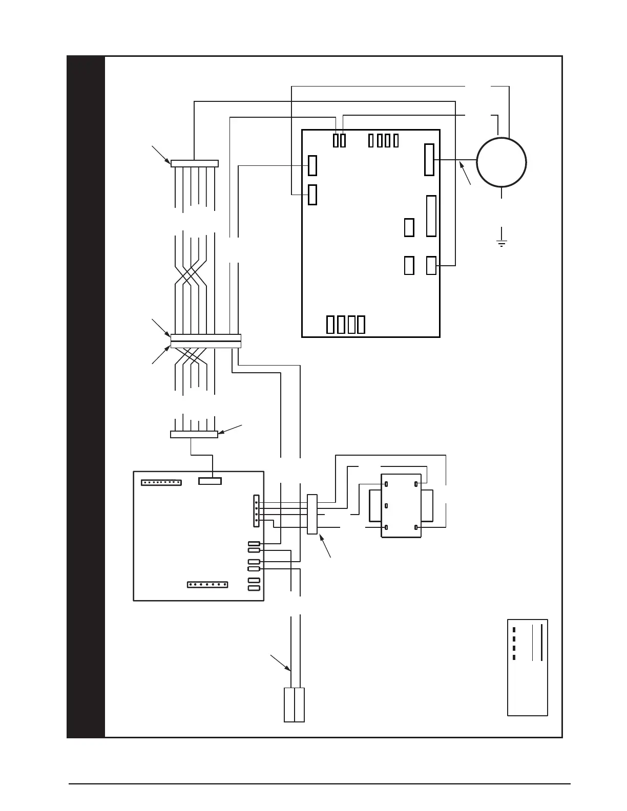
WIRING DIAGRAM
7110770
Air Handler with Variable Speed High Efficiency Motor
Legend
Field Wiring
Factory Wiring:
Low Voltage
High Voltage
¢711077.¤
0510
1
2
240
24 V
208 COM
TRANSFORMER
RC
HEATER PLUG
L
Y1
W2
W1
O
Y/Y2
G
R
C
L2
L1
EAL
HUM
L1 L2 C R
EXPANSION
1 2 3 4 5 6
1 2 3 4 5 6 7 8 9
1 2 3 4 5 6 7 8 9
1 2 3 4 5 6
9-PIN PLUG
9-PIN HOUSING
MOTOR
TEST
EXPANSION
MOTOR
W
Y/Y2
Y1
H
L2 OUT L2 IN
DEHUM
Y1
SENSOR
GND
C DX- DX+ R
BLACK
WHITE
6-PIN PLUG
6-PIN PLUG
BLACK
WHITE
BLACK
WHITE
GRAY
RED
BLACK
HARNESS
HARNESS
GREEN
BROWN
RED
ORANGE
YELLOW
GREEN
BLUE
BROWN
RED
ORANGE
YELLOW
GREEN
BLUE
RED
CUT WIRES TO REMOVE PLUG HOUSING
WHEN HEATER KIT NOT INSTALLED
NOTES:
1. The blower motor
speed tap connection
may not be as shown.
See the Installation Instructions.
2. Disconnect all power before servicing.
3. Transformer may havea dual voltage
primary tap. Match the tap
position with the supply voltage used.
4. If the internal wiring is replaced, use only
105°C copper wire of the same gauge.
BLACK
WHITE
Figure 16. Wiring Diagram for MB7VM Series Air Handler
 Loading...