34
Chapter4.–Installation
4-11. Plumbing Guidelines
1.This drawing is meant to show system piping concept only. Installer is responsible for all equipment and detailing
required by local codes.
2. All closely spaced tees shall be within 4 pipe diameters center to center spacing.
3. A minimum of 6 pipe diameters of straight pipe shall be installed upstream and downstream of all closely spaced tees.
4. The minimum pipe size of DHW piping should be ¾" diameter and Heating piping should be 1" in diameter.
5. Piping shown is Primary/Secondary. System ow (secondary loop) must be greater than the appliance’s primary loop ow.
6. Install a minimum of 12 diameters of straight pipe upstream of all circulators.
7. In a valve-based system, each heating zone has a zone valve which opens when that zone calls for heat.
Each zone thermostat is wired to its corresponding zone valve. Contacts in the zone valves provide a signal to
the appliance to operate when there is a call for heat.
8. Unit is equipped with built-in primary pump for the heating loop. This pump is sized to insure proper ow rate through
the appliance heat exchanger and related piping. On long pipe runs, it is recommended to keep the pump at
maximum speed (setting 3). DO NOT lower it from the factory default.
9. Install a backow preventer valve in the make-up water supply to the unit as required by local codes.
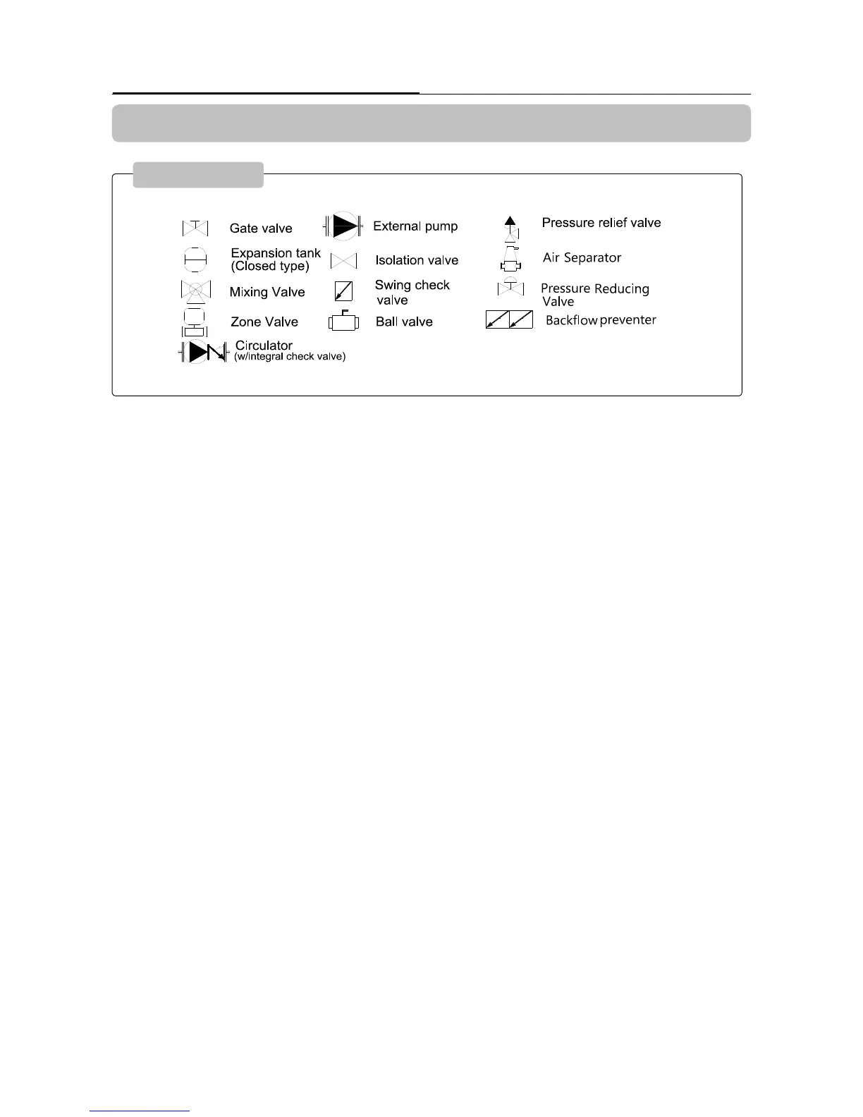
Piping Symbol
Plumbing Guidelines