60
<NR111 (-SV -OD,-DV) / NC250 (-SV,-DV)-ASME / N-0931M (-OD)>
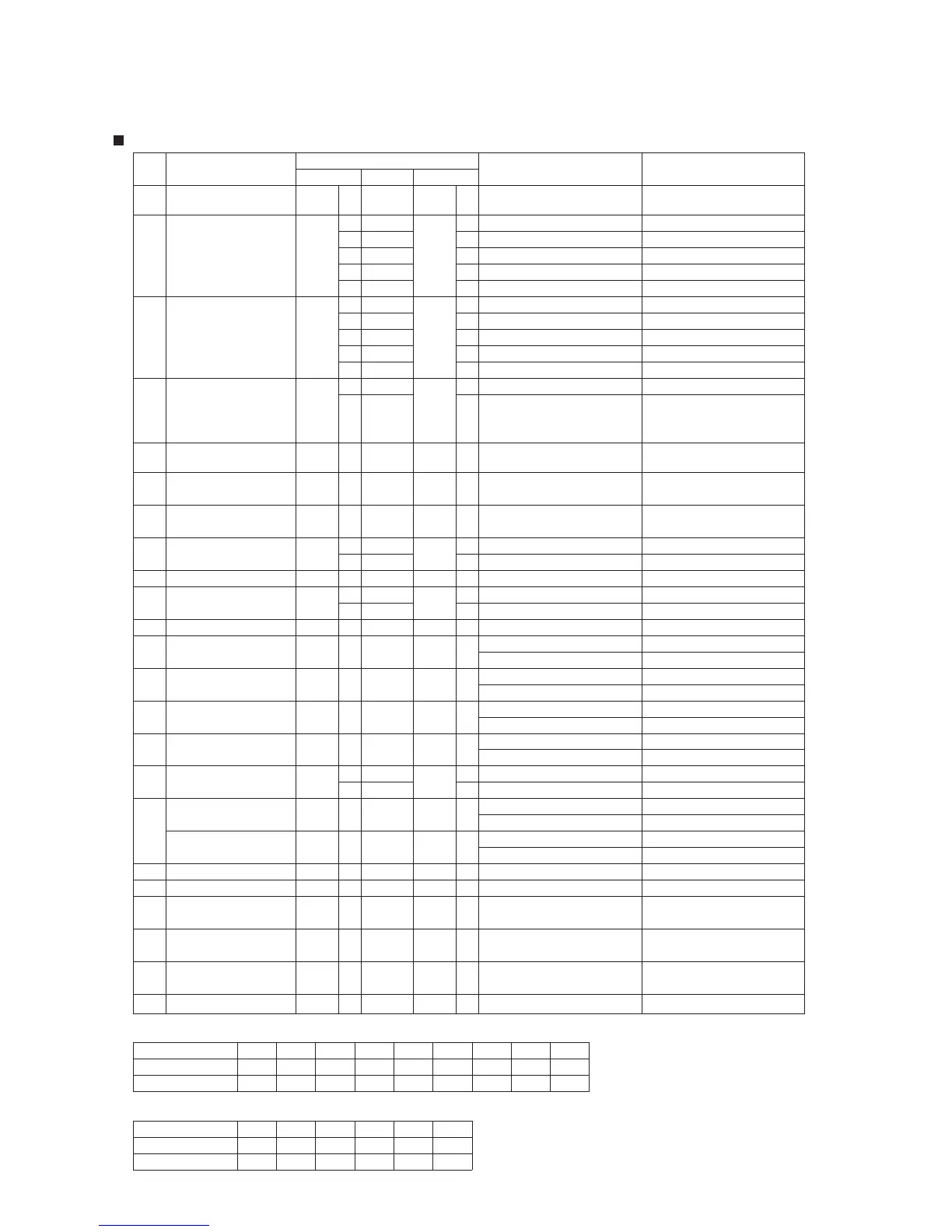
Circuit Board Checkpoints
Coil resistance
When valve is open
0.5 - 2 k
DC 80 - 100 V
7
BR - BL
CN10
3
CN10
17
Gas Solenoid Valve - 3
16
at Flame detection
When no ame is detected
Contact resistance
CN1
6
or less1
High Limit Switch
CN1
3
18
BK - W
DC 1 - 16 V
DC 1 - 16 V
16
15
25
25
BL - O
BL - G
When valve is fully open
DC 1 - 16 V
DC 1V or less
18
29
25
20
BL - BK
Y - BL
CN38
3
25
DC 1 - 16 V
BL - V
17
CN38
Valve
Bypass Flow Control
Y (+) BL (-)
DC 14 - 16 V
7
R - BL
1
(over 6.8Hz)
over 408 pulses/min.
DC 0.5 - 15 V
7
2
Y - BL
CN75
4
Water Flow Sensor
CN75
When valve is fully open
DC 1V or less
DC 1 - 16 V
DC 1 - 16 V
DC 1 - 16 V
29
30
28
27
Y - BL
BL - BK
BL - V
BL - G
24
25
25
25
26
DC 1 - 16 V
CN38
25
CN38
Main Flow Control Valve
2
BL - O
C102
(Power Circuit Board)
Power Supply
(Main Circuit Board)
Power Supply
19
When valve is open
When valve is open
When valve is open
When valve is open
Note 1)
Note 1)
Remarks
2Ω or less
Normal value
DC 1 - 4.5 V
DC 1 - 4.5 V
31
CN38
CN & Pin No.
2
2
CN63
CN63
25
CN38
CN & Pin No.
4
1
CN63
CN63
Part
1
No.
Ref.
5
6
Device (Thermal Fuse)
Overheat Prevention
Water Inlet Thermistor
Water Outlet Thermistor
BL - BL
Circuit board Checkpoints
Wire color
W - W
W - W
Note 1)
When igniter is sparking
Coil resistance
Coil resistance
Coil resistance
10 kHz - 100 kHz
A or lessmDC 0.45
DC 7 - 45 V
DC 10 - 14 V
-
-
-
2
2
CN27
AC 90 - 110 V
DC 80 - 100 V
0.5 - 2 k
0.5 - 2 k
0.5 - 2 k
DC 80 - 100 V
DC 0.3 - 15 V
DC 80 - 100 V
5
7
CN1
CN10
7
CN10
CN10
7
CN27
100 Hz - 400 Hz
2
Coil resistance
Note 2)
10 kHz - 100 kHz
A or moremDC 1
DC 80 - 100 V
W0.5 - 2 k
-
7
-
-
CN10
AC 90 - 110 V
AC 90 - 110 V
DC 13 - 16 V
5
3
CN1
CN92
6
CN63
2
DC 0.7 - 4.4 V
Coil resistance
W50 - 90
4
CN38
1
1
CN78
4
1
CN27
Flame Rod
Fan Motor
2
6
CN10
CN10
8
CN10
CN10
5
Igniter
Solenoid Valve
Primary Gas
Fan Motor
CN27
3
8
9
11
12
10
Gas Solenoid Valve - 1
Gas Solenoid Valve - 2
Gas Proportioning Valve
1
4
1
CN78
CN10
Flame Rod
3
1
CN1
CN92
4
C102
Air Inlet Thermistor
CN63
5
14
15
-
-
-
Gas Solenoid Valve - 4
(Power Circuit Board)
Power Supply
2
CN38
13
BL -
Burnercase
Electrode
BL -
BR - BL
R - BL
Y - BL
BK - W
W - BL
BK - BL
GY - BL
R - BL
Burnercase
BL -
BL -
Electrode
O - BL
W - W
BK - W
W - BK
R - BL
7
Thermistor
Heat Exchanger
CN63
3
CN63
2
DC 1 - 4.5 V
W - W
80
176
70
158
60
140
40
104
122
50
20
12.6
30
8668
30
86
10
50 68
200
32
10
20.6
0-10
34.4
5032
14
-20
106.5
-4
59.6
DC 13 - 16 V
3
CN89
BL - BL
1
CN89
-
Remote Controller
Note 2) t"JS Inlet Thermistor Temperature Characteristics
Note 1)
t*OMFU / Outlet / Heat Exchanger Thermistor Temperature Characteristics
Ω)
Temperature (
˚F)
Temperature (
˚C )
Resistance (k
Ω)
Temperature (
˚F)
Temperature (
˚C )
Resistance (k
Ω
Ω
Ω
Ω
Ω
32 - 212
°F
0 - 100°C
32 - 212° F
0 - 100°C
32 - 212° F
0 - 100°C
23.7 15.5 10.3 7.0
8.0
4.9 3.5 2.5 1.9 1.4
 Loading...