78
Circuit Board Replacement
<NC380-SV-ASME / N-1321M-ASME>
1. Connect electrical power to the unit and wait ten seconds before proceeding to step 2.
2. Within the first ten minutes of connecting electrical power, before turning on the operation
button, hit the "up" or "down" button on the remote controller and hold until the display
blinks "99". If the unit does not go into maintenance mode, unplug the unit and try again.
3. Use the "up" or "down" button on the remote controller to change the maintenance
writer number.
4. Press the "FLOW METER ALARM SET" for 0.5 sec to change the setting ON/OFF.
ON: "priority" lamp flashes.
OFF: "priority" lamp goes off.
5. Change "27" from OFF to ON.
6. Change "FE" and "FC" from OFF to ON in order to access the hidden maintenance writers.
(Display blinks with "A0".)
7. Now the maintenance writers can be accessed by hitting the "up" or "down" button
on the remote controller. Refer to the "Setting list for DIP settings" table for the
correct writer setting.
8. Press the "FLOW METER ALARM SET" for 0.5 sec to change the setting ON/OFF.
ON: "priority" lamp flashes.
OFF: "priority" lamp goes off.
9. When all of the maintenance writers have been set correctly, confirm the settings
by pressing and holding both the "up" and "down" buttons on the remote controller
until the controller emits a beeping noise. The new settings will be lost if this is not done.
F
It is necessary to transfer data when replacing a circuit board. Vital
information about the water heater such as the settings and unit history
will have to be written to the new board. Please transfer data using the
following procedure. If the transfer is not successful, the unit will not
operate and a 73 error code will flash on the remote controller.
When a circuit board is replaced, data must be transferred from the old board, otherwise
a 73 error code will flash on the remote controller and the unit will not operate.
After installing the new circuit board, please transfer data according to the
following procedure:
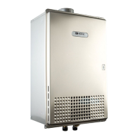
1. With the electrical power disconnected, remove the remote controller connection from
connection number CN89. Also, if connected, undo system controller connections
(SC-101,SC-201) before transferring data.
2. Using the supplied transfer cable, connect the new and old boards by
inserting the cable in connection number CN89 of each board.
3. Reconnect the electrical power. The data transfer will be completed in about 30 seconds.
The unit will signal a successful transfer by rotating the fan and opening and
closing the gas solenoid valve.
4. After confirming a successful transfer, turn the power off. Remove the
cable connecting the new and old circuit boards. Reconnect system controller
and remote controller connections.
5. Follow steps 1-5 and step12 under "Initial Circuit Board Settings" to complete the settings
for the new circuit board.
Data Transferring Procedure
* Be sure to read.
Initial Circuit Board Settings
*If data has already been transferred to the board, follow the resetting procedure.
**Once data has been transferred to a new board, the transfer procedure cannot
be performed again.
1. If this is the first time that the circuit board has been replaced:
Please follow the procedure "Initial Circuit Board Settings".
.
2. If this is the second time that the circuit board has been replaced:
Please follow the procedure "Circuit Board Resetting".
*After replacing the board, check and adjust manifold gas pressure settings to the
values listed in the "Setting list for Gas manifold pressures" table.
*When you cannot transfer data between the boards, please follow the procedures
under "Data Transfer Troubleshooting".
Data Transfer Troubleshooting
*If connected, undo system controller connections.
*A remote controller must be connected to the unit for this procedure.
*After replacing the circuit board, make sure all connections
are made before making the initial circuit board settings.
Connecter Lead attached
with a New Circuit Board
for Servicing
New
Circuit
Board
Reference connection diagram
(for simplification, other connections have been omited)
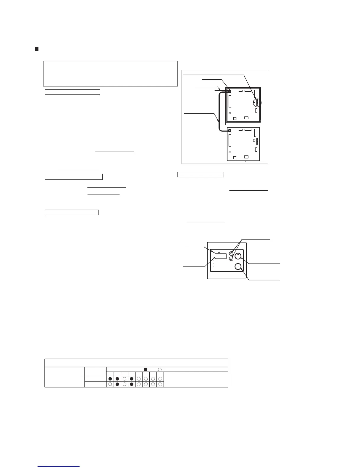
Buttons for adjusting the manifold pressure settings
To Remote Controller
Terminal Block
Disconnect when
transferring
Connecter CN89
89
Circuit Board Resetting
Old
Circuit
Board
89
gal.
1. Install the circuit board into the unit and make all wiring connections.
2. Within the first ten minutes of connecting power to the unit, perform
steps 1 through 4 and step 9 of the "Initial Circuit Board Settings" procedure. This
should result in "A0" blinking on the remote controller.
3. If the "A0" maintenance writer is "ON" ("priority"lamp flashes.), press the
"FLOW METER ALARM SET" button for 0.5 seconds to change "A0" to
"OFF" ("priority"lamp goes off).
4. Press and hold both the "up" and "down" buttons on the remote controller
until the controller emits a beeping noise. The new settings will be lost if this
is not done.
5. If this is a replacement board that had initial problems with data transfer, follow
the "Data Transferring Procedure"
.
[RC-7649M , RC-7650M]
Priority Lamp
PRIORITY
BURNER ON
Setting Button
(Changing Writer No.)
UP
POWER
ON/OFF
Note 1. To cancel the settings, let the controller sit for 10 minutes,
or turn on the operation button. The information set previously
will be canceled. To change settings again, follow steps 1 through 10.
Note 2. Only change data as listed in the "Circuit board DIP settings" table.
Setting list for DIP settings
(check the rating plate for model and gas type)
Display
(Writer No.)
instantly or death from scalding.
before using this appliance.
temperature before entering shower
over 125 F can cause severe burns
Hot Water Heater temperature
Check actual and controller water
Please read instructions carefully
WARNING
or bath.
RC-7649M
Operation Button
Setting Button
(Swiching ON/OFF)
DOWN
ALARM SET
FLOW METER
(check the rating plate for model and gas type)
NC380-SV-ASME/
N-1321M-ASME
Model
Gas type
LPG
Natural
Circuit board DIP setting ( :ON :OFF)
A1 A2 A4 A5 A6 A8 A9 AF
"Refer to Page.82 - 86"
 Loading...