EasyManua.ls Logo

Nortek FT4BE-K User Manual

Nortek FT4BE-K
20 pages
To Next Page IconTo Next Page
Page #1 background imageLoading...
Page #1 background image
INSTALLATION INSTRUCTIONS
14 SEER
HEAT PUMP MAINTENANCE ............................... 8
REFRIGERANT CHARGING .................................9
Charging the Unit in AC Mode with
Outdoor Temperatures Above 55° F ......................9
CHARGING CHARTS - COOLING ONLY ........... 10
Figure 5. Charging Chart for 1.5 Ton Units ........ 10
Figure 6. Charging Chart for 2 Ton Units ........... 11
Figure 7. Charging Chart for 2.5 Ton Units ........ 11
Figure 8. Charging Chart for 3 Ton Units ........... 12
Figure 9. Charging Chart for 3.5 Ton Units ........ 12
Figure 10. Charging Chart for 4 Ton Units ......... 13
Figure 11. Charging Chart for 5 Ton Units ......... 13
HEAT MODE VERIFICATION TABLES ................ 14
Table 4. Verification Table for 1.5 Ton Units ....... 15
Table 5. Verification Table for 2 Ton Units .......... 15
Table 6. Verification Table for 2.5 Ton Units ....... 15
Table 7. Verification Table for 3 Ton Units .......... 15
Table 8. Verification Table for 3.5 Ton Units ....... 16
Table 9. Verification Table for 4 Ton Units .......... 16
Table 10. Verification Table for 5 Ton Units ........ 16
WIRING DIAGRAMS ............................................ 17
Figure 12. Wiring Diagram for 1.5 - 5 Ton
Units Equipped with CoreSense
TM
.................... 17
Figure 13. Wiring Diagram for 1.5 - 5 Ton
Units NOT Equipped with CoreSense
TM
............ 18
Figure 14. Wiring Diagram for 1.5 - 5 Ton
Units Equipped with Low Pressure Switch ........ 19
INSTALL. / PERFORMANCE CHECKLIST ......... 20
REPLACEMENT PARTS ...................................... 20
IMPORTANT SAFETY INFORMATION .................2
HEAT PUMP INSTALLATION ................................3
General Information ..............................................3
Before You Install this Unit .....................................3
Locating the Heat Pump........................................3
Packaging Removal .............................................. 3
Ground Level .........................................................3
Rooftop..................................................................3
Connecting Refrigerant Tubing Between the
Indoor & Outdoor Unit ........................................... 4
Outdoor Orifice Removal & Installation ................. 4
ELECTRICAL WIRING ...........................................5
Pre - Electrical Checklist ....................................... 5
Line Voltage ...........................................................5
Grounding .............................................................6
Thermostat / Low Voltage Connections .................6
CoreSense
TM
Diagnostics Module .........................6
Compressor Protection ....................................... 6
Resetting Alert Codes .........................................7
STARTUP & ADJUSTMENTS ...............................8
Pre - Start Checklist .............................................. 8
Start-up Procedures ..............................................8
Air Circulation - Indoor Blower ..............................8
Short Cycle Protection .......................................... 8
System Cooling .....................................................8
System Heating .....................................................8
Defrost Control Board Test Pins ............................8
DO NOT DESTROY. PLEASE READ CAREFULLY AND KEEP IN A SAFE PLACE FOR FUTURE REFERENCE.
IMPORTANT
ATTENTION INSTALLERS:
It is your responsibility to know this product better than your customer. This includes being able to install the product
according to strict safety guidelines and instructing the customer on how to operate and maintain the equipment for
the life of the product. Safety should always be the deciding factor when installing this product and using common
sense plays an important role as well. Pay attention to all safety warnings and any other special notes highlighted
in the manual. Improper installation of the furnace or failure to follow safety warnings could result in serious injury,
death, or property damage.
These instructions are primarily intended to assist qualified individuals experienced in the proper installation of
this appliance. Some local codes require licensed installation/service personnel for this type of equipment. Please
read all instructions carefully before starting the installation. Return these instructions to the customer’s package
for future reference.
SPLIT SYSTEM HEAT PUMP WITH MICROCHANNEL COILS
T4BE - 018, 024, 030, 036, 042, 048, & 060 (1.5, 2, 2.5, 3, 3.5, 4, & 5 Ton) Series
SINGLE PHASE MODELS
Question and Answer IconNeed help?

Do you have a question about the Nortek FT4BE-K and is the answer not in the manual?

Nortek FT4BE-K Specifications

General IconGeneral
BrandNortek
ModelFT4BE-K
CategoryHeat Pump
RefrigerantR-410A
Power Supply208-230V/1Ph/60Hz

Summary

Important Safety Information

Electrical Shock, Fire, or Explosion Hazard

Hazards related to electrical shock, fire, and explosion during servicing.

R410A Refrigerant Handling Warning

Warnings regarding R410A refrigerant and qualified personnel for installation and service.

R-410A Refrigerant Use Caution

Caution against using any refrigerant other than R-410A to prevent unit damage.

Heat Pump Installation

General Information

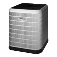
Overview of split system heat pumps for outdoor installation and maintenance.

Before You Install the Heat Pump

Steps and checks required before proceeding with heat pump installation.

Locating the Heat Pump

Guidelines for selecting an optimal location for the outdoor heat pump unit.

Packaging Removal

Instructions for safely removing packaging and checking for shipping damage.

Ground Level Installation

Requirements for ground-level mounting pads and clearances.

Rooftop Installation

Considerations for rooftop mounting, structural support, and clearances.

Connecting Refrigerant Tubing

Procedures for connecting refrigerant lines between indoor and outdoor units.

Outdoor Orifice Removal & Installation

Guidance on changing the outdoor unit orifice based on indoor coil matching.

Electrical Wiring

Pre-Electrical Checklist

Essential checks before making electrical connections to the unit.

Line Voltage Wiring

Details on connecting line voltage power supply, disconnects, and circuit protection.

Grounding Requirements

Importance and methods for proper electrical grounding to prevent hazards.

Thermostat / Low Voltage Connections

Instructions for connecting the 24 VAC control circuit and thermostat wiring.

CoreSense™ Diagnostics Module

Overview of the CoreSense module for troubleshooting heat pump system failures.

Start Up & Adjustments

Pre-Start Check List

Final checks before energizing the unit for startup.

Start-Up Procedures

General steps for initial unit startup, including crankcase heater warm-up.

Air Circulation - Indoor Blower

Verifying proper operation of the indoor blower fan.

Short Cycle Protection

Testing the unit's short cycle protection mechanism.

System Cooling Operation

Steps to verify proper operation in cooling mode.

System Heating Operation

Steps to verify proper operation in heating mode.

Defrost Control Board Test Pins

How to use test pins to bypass timers or initiate defrost cycles.

Refrigerant Charging

Charging Guidelines

General notes on refrigerant charging procedures and system requirements.

Charging the Unit in AC Mode

Procedure for charging the unit in air conditioning mode above 55°F.

Refrigerant Charging Charts - Cooling Only

Application notes for using cooling mode charging charts.

Heat Mode Verification Tables

Application Notes

Instructions for using heating-mode charge verification tables.

Wiring Diagrams

Wiring Diagram for 1.5 - 5 Ton Models (Units Equipped With CoreSense™ Diagnostic Module)

Electrical schematic for units equipped with the CoreSense diagnostic module.

Wiring Diagram for 1.5 - 5 Ton Models (Units NOT Equipped With CoreSense™)

Electrical schematic for units not equipped with the CoreSense diagnostic module.

Wiring Diagram for 1.5 - 5 Ton Models (Units Equipped with Low Pressure Switch)

Electrical schematic for units equipped with a low pressure switch.

Installation / Performance Check List

Electrical System Checks

Checklist items for verifying electrical connections and voltage.

Refrigeration System Checks

Checklist items for verifying refrigeration system parameters.

Replacement Parts

Information on ordering replacement parts for the unit.

Related product manuals