5
• Thethermostatshouldbemountedabout5feetabove
the floor on an inside wall. DO NOT install the thermostat
on an outside wall or any other location where its
operation may be adversely affected by radiant heat from
fireplaces, sunlight, or lighting fixtures, and convective
heat from warm air registers or electrical appliances.
Refer to the thermostat manufacturer’s instruction sheet
for detailed mounting and installation information.
on the outdoor unit data label. Any other wiring methods
must be acceptable to authority having jurisdiction.
• Theoutdoorunitrequiresbothpowerandcontrolcircuit
electrical connections. Refer to the wiring diagram
(Figure 8) for identification and location of outdoor unit
field wiring interfaces. Make all electrical connections in
accordance with all applicable codes and ordinances.
• Overcurrentprotectionmustbeprovidedatthebranch
circuit distribution panel and sized as shown on the unit
rating label and according to applicable local codes.
See the unit rating plate for minimum circuit ampacity
and maximum overcurrent protection limits.
• Providepowersupplyfortheunitinaccordancewiththe
unit wiring diagram, and the unit rating plate. Connect
the line-voltage leads to the terminals on the contactor
inside the control compartment.
• Useonlycopperwireforthelinevoltagepowersupply
to this unit as listed in Table 2. Use proper code agency
listed conduit and a conduit connector for connecting
the supply wires to the unit. Use of rain tight conduit is
recommended.
• 208/230Voltunitsareshippedfromthefactorywired
for 230 volt operation. For 208V operation, remove the
lead from the transformer terminal marked 240V and
connect it to the terminal marked 208V.
• Optionalequipmentrequiringconnectiontothepower
or control circuits must be wired in strict accordance of
the NEC (ANSI/NFPA 70), applicable local codes, and
the instructions provided with the equipment.
Grounding
WARNING:
The unit cabinet must have an uninterrupted or
unbroken electrical ground to minimize personal
injury if an electrical fault should occur. Do not
use gas piping as an electrical ground!
This unit must be electrically grounded in accordance
with local codes or, in the absence of local codes, with
the National Electrical Code (ANSI/NFPA 70) or the CSA
C22.1 Electrical Code. Use the grounding lug provided in
the control box for grounding the unit.
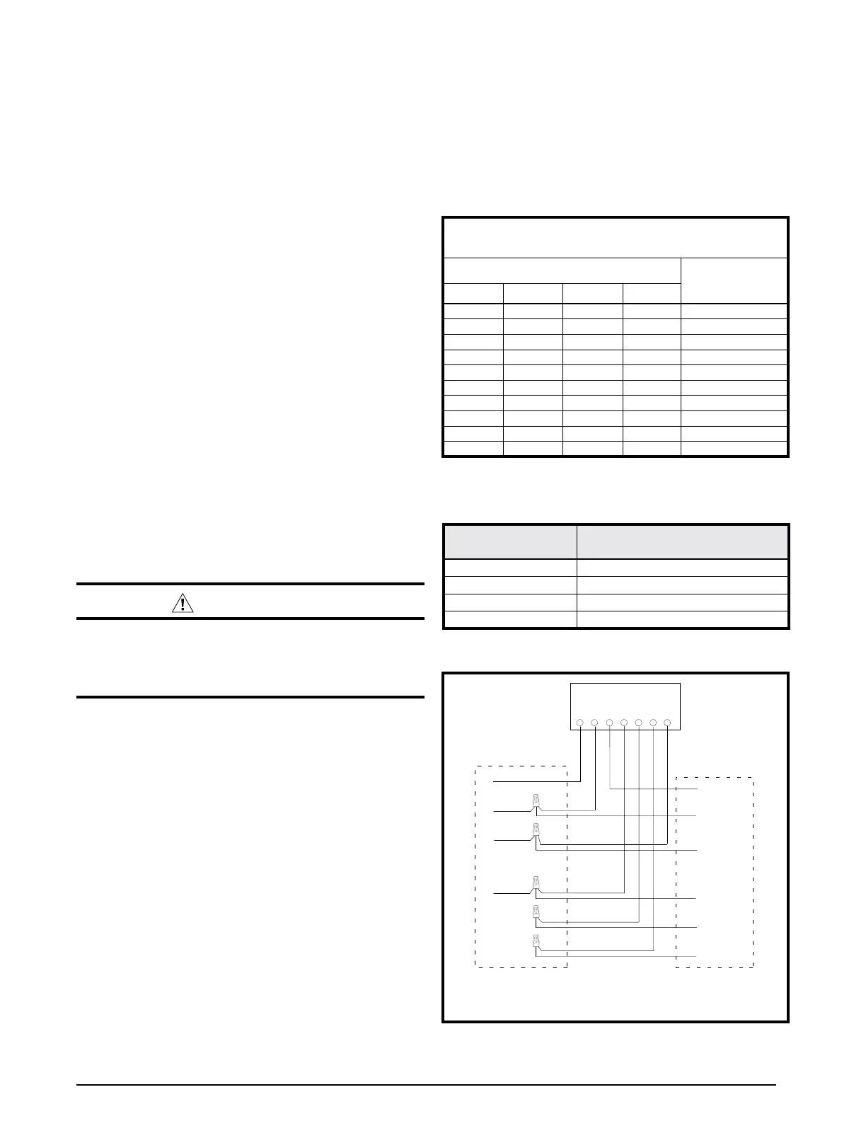
• Thermostatconnectionsshouldbemadeinaccordance
with the instructions supplied with the thermostat and
the indoor equipment. A typical installation with a heat
pump thermostat and air handler is shown in Figure 2.
• Theoutdoorunitisdesignedtooperatefroma24VAC
Class II control circuit. The control circuit wiring must
comply with the current provisions of the NEC (ANSI/
NFPA 70) and with applicable local codes having
jurisdiction.
• Thelowvoltagewiresmustbeproperlyconnectedto
the units low voltage terminal block. Recommended
wire gauge and wire lengths for typical thermostat
connections are listed in Table 3.
G
R
W2
C
E
O
Y
Thermostat
Green
Red
White
G
R
Black
O
Y1 IN
R
C
Air Handler
Heat Pump
(OD Section)
C
W
W2 OUT
W2 IN
Figure 2. Typical Thermostat Connections
COPPER WIRE SIZE — AWG
SUPPLY WIRE LENGTH-FEET
SUPPLY
CIRCUIT
AMPACITY200 150 100 50
6 8 10 14 15
4 6 8 12 20
4 6 8 10 25
4 4 6 10 30
3 4 6 8 35
3 4 6 8 40
2 3 4 6 45
2 3 4 6 50
2 3 4 6 55
1 2 3 4 60
Wire Size based on N.E.C. for 60° type copper conductors.
Table 2. Copper Wire Size
THERMOSTAT
WIRE GAUGE
MAXIMUM RECOMMENDED
THERMOSTAT WIRE LENGTH (FT)
24 25
22 45
20 70
18 110
Table 3. Thermostat Wire