6
3. After approximately 5 minutes, verify the outdoor unit
energizes and the temperature of the discharge air is
cooler than the room temperature.
System Cooling
1. Set the thermostat’s system mode to COOL and the
fan mode to AUTO. Gradually lower the thermostat
temperature setpoint below room temperature and
verify the outdoor unit and indoor blower energize.
2. Verify blower wheel is spinning in direction indicated by
arrow. Feel the air being circulated by the indoor blower
and verify that it is cooler than ambient temperature.
Listen for any unusual noises. If unusual sounds occur,
determine the source of the noise and correct as
necessary.
3. Verify HI and LO refrigerant pressures.
4. Allow the system to operate for several minutes and then
set the temperature selector above room temperature.
Verify the fan and compressor cycle off with the
thermostat. NOTE: The blower should also stop unless
fan switch is set to the ON position.
System Heating
1. Set the thermostat's system mode to HEAT and the
temperature mode to below room temperature.
2. Verify the outdoor unit and indoor fan stop running. After
5 minutes, increase the temperature on the thermostat
to it's maximum setting.
3. Verify the outdoor unit and indoor blower energize. Feel
the air being circulated by the indoor blower and verify
that it is warmer than ambient temperature. Listen for
any unusual noises. If unusual sounds occur, determine
the source of the noise and correct as necessary.
• Placingajumperbetweenthetestpinsforlessthan1
second will bypass the Anti-Short Cycle Timer.
• Placingajumperbetweenthetestpinsformorethan1
second will force the unit into a defrost cycle. As soon
as the jumper is removed, the defrost cycle will end as
determined by the typical criteria.
• Verify the Status Indicator (on the control board)
against the codes listed in Table 5 to determine proper
diagnostic description.
START UP & ADJUSTMENTS
Pre-Start Check List
√ Verify the unit is level and has sufficient clearances for
unobstructed airflow.
√ Verify the outdoor coil and top of the unit are free from
obstructions and debris, and all equipment access/
control panels are in place.
√ Verify that the line voltage power leads are securely
connected and the unit is properly grounded.
√ Verify that the low voltage wires are securely connected
to the correct leads on the low voltage terminal strip.
√ Verify that the power supply branch circuit overcurrent
protection is sized properly.
√ Verify that the thermostat is wired correctly.
Start-Up Procedures
WARNING:
This unit is equipped with a crankcase heater.
Allow 24 hours prior to continuing the start up
procedures to allow for heating of the refrigerant
compressor crankcase. Failure to comply may
result in damage and could cause premature
failure of the system. This warning should be
followed at initial start up and any time the power
has been removed for 12 hours or longer.
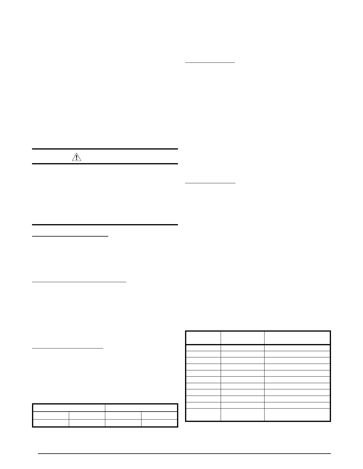
Operating Temperatures
This equipment has been designed to operate within the
temperatures specified inTable 4. Running the equipment
in heating at higher than 70° F may require the use of a
Heat Pump Mild Weather Control Kit or changing over to
emergency or auxiliary heating.
Air Circulation - Indoor Blower
1. Set the thermostat system mode on OFF and the fan
mode to ON.
2. Verify the blower runs continuously. Check the air delivery
at the supply registers and adjust register openings for
balanced air distribution. If insufficient air is detected,
examine ductwork for leaks or obstructions.
3. Set the thermostat fan mode to AUTO and verify the
blower stops running.
Short Cycle Protection
1. Set the thermostat system mode to COOL. Observe the
temperature setting of the thermostat and gradually raise
the set-point temperature until the unit de-energizes.
2. Immediately lower the set point temperature of the
thermostat to its original setting and verify that the
indoor blower is energized and outdoor unit remains
de-energized.
STATUS
INDICATOR
STATUS
TYPE
DIAGNOSTIC
DESCRIPTION
C1
Operating Status Cooling, 1st Stage
H1
Operating Status Heating, 1st Stage
SC
Operating Status Anti Short Cycle Timer
OF
Operating Status Defrost
_.
Operating Status Power on, no call for operation
01
Fault Pressure switch, low
02
Fault Pressure switch, high
03
Fault Temperature Sensor, Ambient
04
Fault Temperature Sensor, Coil
05
Fault Board
OF
(FLASHING)
Input Error
Forced defrost - test short
applied longer than 11 minutes
Table 5.
Table 4. Heat Pump Operating Temperatures
COOLING HEATING
MIN (°F) MAX (°F) MIN (°F) MAX (°F)
60 115 -10 70
 Loading...