The provided document is an owner's manual for the Nortek Global HVAC, LLC Wired Remote Controller WRC4. This device serves as a control interface for various indoor HVAC units, allowing users to manage operation modes, temperature, fan speed, and other functions.
Function Description
The WRC4 is a wired remote controller designed to provide comprehensive control over compatible indoor HVAC units. Its primary function is to allow users to turn the unit on/off, select operation modes (Auto, Cooling, Dry, Fan, Heating), adjust the set temperature, and control the fan speed (High, Middle, Low, Auto).
Beyond basic operation, the WRC4 offers several advanced functions:
- Timer Setting: Users can set a timer for the unit to turn off or on, with a range of 0.5 to 24 hours, adjustable in 0.5-hour increments.
- Swing Function: Activates or deactivates the automatic swing of the indoor unit's louvers.
- Sleep Setting: Engages a sleep mode that gradually adjusts the set temperature over time (increasing in Cooling/Dry mode, decreasing in Heating mode) to optimize comfort and energy efficiency during sleep. This function currently supports only "Sleep 1."
- Turbo Setting: Enables the unit to operate at high fan speed for rapid cooling or heating, quickly bringing the room temperature closer to the set value.
- E-heater Setting (Auxiliary Electric Heating): In Heating mode, this function can be activated to improve heating efficiency. It can turn on automatically when the unit enters Heating mode.
- Blow Setting: After the unit is turned off in Cooling or Dry mode, this function runs the indoor fan at a low speed for 2 minutes to evaporate water from the evaporator, preventing mildew. This function is unavailable in Fan or Heating mode.
- Lock Function: Allows users to lock the controller to prevent unintended operation. When locked, no other buttons will respond.
- Memory Function: If activated, the indoor unit will resume its original setting state (On/Off, Mode, set temperature, set fan speed, and Lock function) after a power failure and subsequent power recovery. If not set, the unit defaults to an off state after power recovery.
The wired controller is a general model, meaning some functions may not be available for all types of units. The manual advises referring to the specific unit's owner's manual for details on unavailable functions, noting that their setting will not affect the unit's operation. The remote receiver can be either in the indoor unit or the wired controller, depending on the specific model.
Important Technical Specifications
- Temperature Setting Range: 61°F to 86°F (16°C to 30°C) in Cooling, Dry, Fan, or Heating modes. In Auto mode, the setting temperature is unadjustable.
- Timer Range: 0.5 to 24 hours, adjustable in 0.5-hour increments.
- Communication Distance: The communication distance between the main board and the wired remote controller can be up to 20 meters, with a standard distance of 8 meters.
- Communication Interface: CN1 is the 485 communication interface, used for connecting the 4-core communication wire. CN2 and CN3 are needle stands for connecting the smart zone controller.
- Node Address Support: The WRC4 can support up to 16 communication node addresses when connected to a smart zone controller.
- DIP Switch: A 2-bit DIP switch on the main board allows configuration for the last wired controller in a control system (1-bit "on," 2-bit "off"), while other controllers remain at the ex-factory "off" setting.
Usage Features
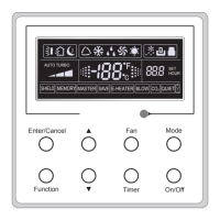
The WRC4 features an LCD display that shows various symbols indicating the current operational status, including:
- Swing function (1)
- Sleep function (2)
- Running modes (Cooling, Dry, Fan, Heating) (3)
- Defrosting function (4)
- Gate-control function (5)
- Lock function (6)
- Fan speed (High, Middle, Low, Auto) (7)
- Shield functions (8)
- Turbo function (9)
- Memory function (10)
- Master wired remote controller (11 - currently unavailable)
- Blinking indicator for button operation (12)
- Energy-saving function (13 - currently unavailable)
- Ambient/preset temperature value (14)
- Electric auxiliary heating function (15)
- Blow function (16)
- Timing value (17)
- Quiet function (18 - currently unavailable)
- SET (displayed under debugging mode) (19)
The controller has eight buttons: Enter/Cancel, Up arrow, Down arrow, Fan, Mode, Function, Timer, and On/Off.
- On/Off: Toggles the unit's power.
- Mode: Cycles through operation modes (Auto-Cooling-Dry-Fan-Heating).
- Up/Down Arrows: Adjust temperature or timing values.
- Fan: Cycles through fan speeds (Auto-Low-Middle-High).
- Timer: Initiates timer setting for on/off operations.
- Function: Cycles through advanced functions (Turbo, Save, E-heater, Blow).
- Enter/Cancel: Confirms or cancels selected functions/settings.
Special button combinations enable additional features:
- Up + Mode (5s under off state): Toggles Memory function.
- Fan + Down (under off state): Displays unit type (cooling-only or heating-and-cooling).
- Up + Down (5s under off state or no malfunction): Enters/exits Lock state.
- Mode + Down (5s under off state): Switches between Celsius and Fahrenheit scales.
- Function + Timer (5s under off state): Enters commissioning status for temperature sensor selection or fan speed level setting.
The temperature sensor selection allows choosing between the return air temperature sensor, the wired controller's sensor, or a combination depending on the mode. If not manually set, the wired controller automatically selects the sensor type based on the connected indoor unit model (e.g., cassette, duct, floor-ceiling types use option 3; others use option 1).
Maintenance Features
- Error Display: In case of system malfunction, error codes (e.g., F0) are displayed on the LCD. If multiple errors occur, their codes will be displayed circularly. Users are advised to turn off the unit and contact professional personnel if an error occurs.
- Installation and Dismantlement: The manual provides detailed instructions for connecting the signal line, installing the wired remote controller on a wall using a socket box, soleplate, and screws, and then attaching the front panel. It also outlines the process for dismantlement.
- Wiring Precautions: Emphasizes the importance of separating signal/communication lines from power cords by a minimum of 20cm to prevent electromagnetic interference. If the installation location is prone to interference, shielding twisted pair lines must be used for signal and communication.
- Commissioning Status: Allows for advanced configuration of temperature sensor selection and fan speed levels, accessible by pressing "Function" and "Timer" for five seconds under the OFF state. Settings made in this mode are memorized upon confirmation with "Enter/Cancel." If no operation occurs for 20 seconds, the controller reverts to the previous state without saving changes.