4-8 Version 2 Enhanced Alarm System
297–1001–122 Standard 06.01 August 1999
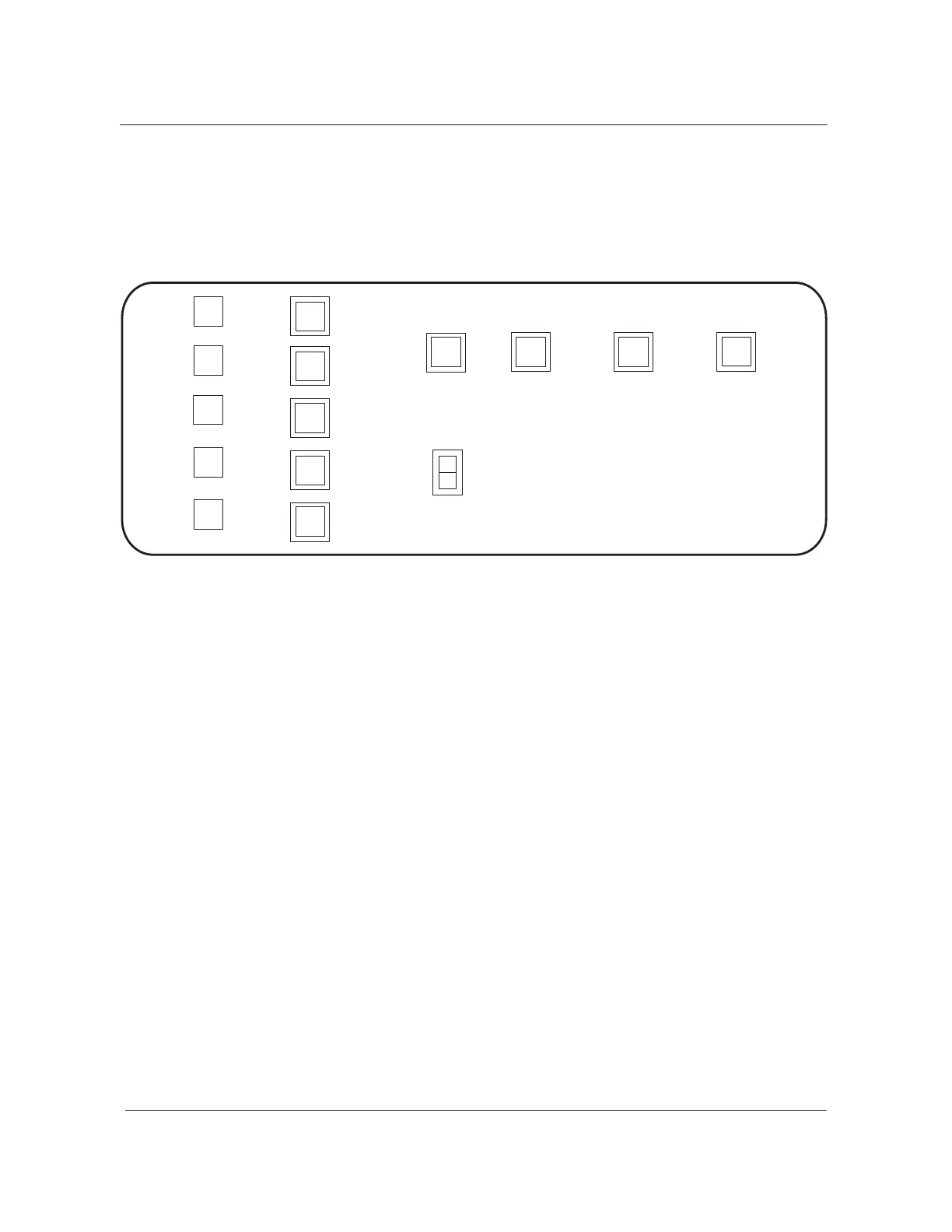
the alarm display panel are the same as those on the ACD. Table 4-1
describes these functions.
Figure 4-4
Alarm display panel
A
WW
W
Power
Dist
Center
Audible
Alarm
Reset
Night Alarm
Transfer
Alarm
Grouping
Alarm
Transfer
Office
Alarm
System
Legend:
Lamp A = amber
Lamp G = green
Lamp R = red
Lamp W= white
Lamp Y = yellow
R
A
R
A
W
Critical
System
Major
System
Minor
System
Major
Other
System
Minor
Other
System
Power
Dist
Center
ABS
Critical
Power
Plant
Major
Power
Plant
Minor
Power
Plant
Office
Alarm
Unit
R
A
W
Y
G
Exit alarm panel
The exit alarm panel (NT0X64) is near the main exit door on each floor in a
multi-floored DMS office. Figure 4-5 shows this panel. Normally, you can
install a maximum of four exit alarm panels in a DMS office. For more
information, refer to the Alarm extension circuits section in this chapter.
The exit alarm panels direct maintenance personnel to the area or floor of
the office where detection of the alarm condition occurred. The exit alarm
panels provide remote controls for the night alarm transfer and alarm
grouping circuits. The functions of the lamps and switches on the exit alarm
panels are as follows:
• The night alarm transfer switch and lamp have the same functions as
these devices on the ACD. These functions are described in Table 4-1.
• The alarm grouping switch and lamp have the same functions as these
devices on the ACD. These functions are described in Table 4-1.
• The yellow power plant lamp lights to signal an alarm condition in the
DMS power plant.
 Loading...