Version 2 Enhanced Alarm System 4-9
DMS-100 Family Alarm System Description Reference Manual BASE12
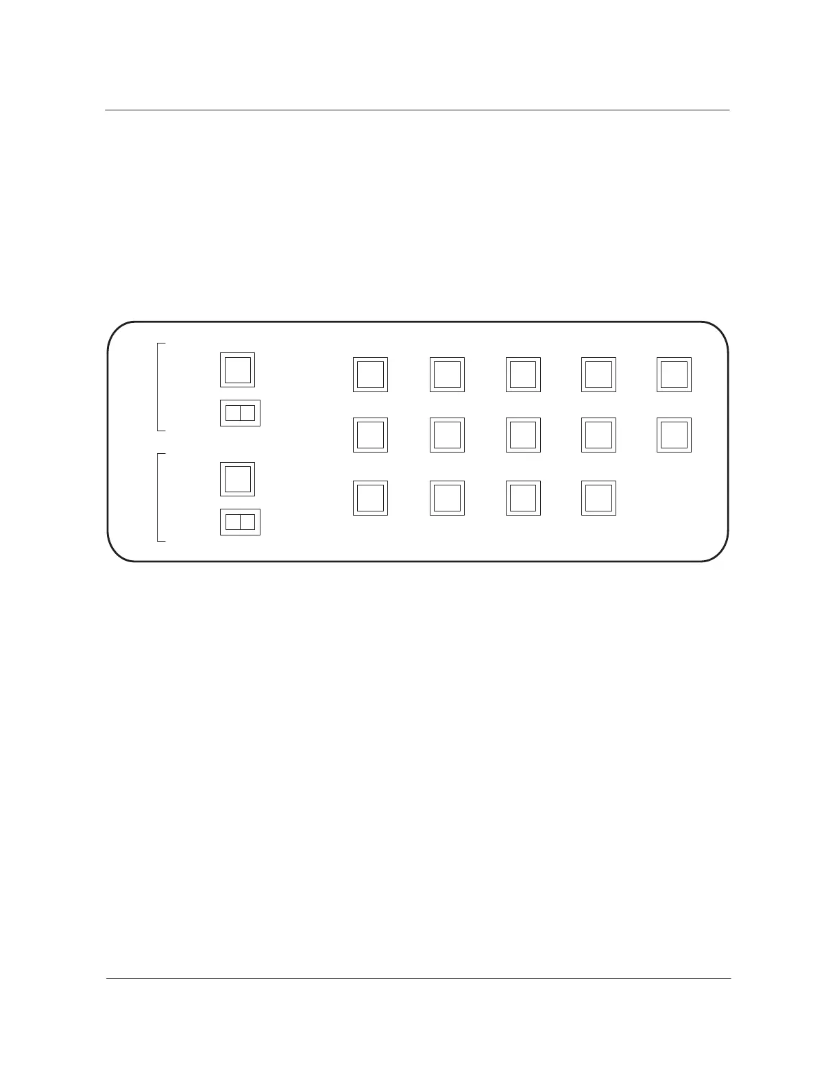
• The yellow trunk test center lamp lights to signal an incoming call on
101 test line in the TTC. The lamp lights if night alarm transfer is
active.
• The yellow exit pilot lamps are numbered 1 through 12. The pilot lamps
are available for each floor with an alarm reporting system, DMS floor,
or non-DMS floor. An alarm origination on a specified floor lights the
exit pilot lamp representing that floor on each exit alarm panel.
Figure 4-5
Exit alarm panel
Y
W
W
Night
Alarm
Transfer
2
Office
Alarm
System
Legend:
Lamp W= white
Lamp Y = yellow
Alarm
Grouping
Trunk
Test
Center
5811
3
Power
Plant
6912
47101
Y
Y
Y
Y
Y
Y
Y
Y
Y
Y
Y
Y
Y
Equipment aisle visual alarms
Each equipment aisle in the DMS office has the red end-aisle pilot lamps.
These lamps light if an FSP detects a fault in the aisle. Each FSP in an aisle
has a frame fail lamp that lights to indicate which frame in the aisle
generates the alarm. The FSP for frames with cooling units have a fan fail
lamp. Chapter 6 contains a description of the circuits associated with the
FSP alarms.
Alarm extension circuits
You require alarm extension circuits when audible or visual alarm
requirements are not met by the two main audible panels and four exit alarm
panels normally available.
The audible and visual alarm extension circuit (NT5X85AA) is an applique
circuit. When mounted on the miscellaneous frame (NT0X02AB), this
circuit allows up to four additional audible alarm panels. This circuit also
 Loading...