Page 2 of 6 — DN-6720 • 08/23/04
FMM-1 Operation — Each FMM-1 uses one of 159 avail-
able module addresses on an SLC loop. It responds to regu-
lar polls from the control panel and reports its type and the
status (open/normal/short) of its Initiating Device Circuit (IDC).
A flashing LED indicates that the module is in communica-
tion with the control panel. The LED latches steady on alarm
(subject to current limitations on the loop).
FMM-1 Specifications
Nominal operating voltage: 15 to 32 VDC.
Maximum current draw: 5.1 mA (LED on).
Maximum operating current: 375 µA (LED flashing).
EOL resistance: 47K ohms.
Temperature range: 32°F to 120°F (0°C to 49°C).
Humidity range: 10% to 93% noncondensing.
Dimensions: 4.5" (11.43 cm) high x 4" (10.16 cm) wide x
1.25" (3.175 cm) deep. Mounts to a 4" (10.16 cm) square x
2.125" (5.398 cm) deep box.
FMM-101 MINI MONITOR MODULE
• Built-in type identification automatically identifies this de-
vice as a monitor module to the panel.
• Powered directly by two-wire FACP. No additional power
required.
• High noise (EMF/RFI) immunity.
• Tinned, stripped leads for ease of wiring.
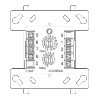
• Direct-dial entry of address: 01 – 159 on FlashScan® sys-
tems, 01 – 99 on CLIP systems.
The FMM-101 Mini Monitor Module can be installed in a
single-gang junction directly behind the monitored unit. Its
small size and light weight allow it to be installed without rigid
mounting. The FMM-101 is intended for use in intelligent,
two-wire systems where the individual address of each mod-
ule is selected using rotary switches. It provides a two-wire
initiating device circuit for normally-open-contact fire alarm
and security devices. The FMM-101 can be used to replace
MMX-101 module in existing systems.
FMM-101 Applications — Use to monitor a single de-
vice or a zone of four-wire smoke detectors, manual fire alarm
pull stations, waterflow devices, or other normally-open dry-
contact devices. May also be used to monitor normally-open
supervisory devices with special supervisory indication at the
control panel. Monitored circuit/device is wired as an NFPA
Style B (Class B) Initiating Device Circuit. A 47K ohm End-of-
Line Resistor (provided) terminates the circuit.
FMM-101 Operation — Each FMM-101 uses one of 159
available module addresses on an SLC loop. It responds to
regular polls from the control panel and reports its type and
the status (open/normal/short) of its Initiating Device Circuit
(IDC).
FMM-101 Specifications
Nominal operating voltage: 15 to 32 VDC.
Maximum operating current: 375 µA.
EOL resistance: 47K ohms.
Temperature range: 32°F to 120°F (0°C to 49°C).
Humidity range: 10% to 93% noncondensing.
Dimensions: 1.3" (3.302 cm) high x 2.75" (6.985 cm) wide x
0.5" (1.270 cm) deep.
Wire length: 6" (15.24 cm) minimum.
FZM-1 INTERFACE MODULE
• Supports compatible two-wire smoke detectors.
• Supervises IDC wiring and connection of external power
source.
• High noise (EMF/RFI) immunity.
• SEMS screws with clamping plates for ease of wiring.
• Direct-dial entry of address: 01 – 159 on FlashScan® sys-
tems, 01 – 99 on CLIP systems.
• LED flashes during normal operation (this is a program-
mable option).
• LED latches steady to indicate alarm on command from
control panel.
The FZM-1 Interface Module is intended for use in intelli-
gent, addressable systems, where the individual address of
each module is selected using built-in rotary switches. This
module allows intelligent panels to interface and monitor two-
wire conventional smoke detectors. It transmits the status
(normal, open, or alarm) of one full zone of conventional de-
tectors back to the control panel. All two-wire detectors be-
ing monitored must be UL compatible with the module. The
FZM-1 has a panel-controlled LED indicator and can be used
to replace MMX-2 modules in existing systems.
FZM-1 Applications — Use the FZM-1 to monitor a zone
of two-wire smoke detectors. The monitored circuit may be
wired as an NFPA Style B (Class B) or Style D (Class A) Ini-
tiating Device Circuit. A 3.9 K ohm End-of-Line Resistor (pro-
vided) terminates the end of the Style B or D (class B or A)
circuit (maximum IDC loop resistance is 25 ohms). Install ELR
across terminals 8 and 9 for Style D application.
FZM-1 Operation — Each FZM-1 uses one of 159 avail-
able module addresses on an SLC loop. It responds to regu-
lar polls from the control panel and reports its type and the
status (open/normal/short) of its Initiating Device Circuit (IDC).
A flashing LED indicates that the module is in communica-
tion with the control panel. The LED latches steady on alarm
(subject to current limitations on the loop).
FZM-1 Specifications
Nominal operating voltage: 15 to 32 VDC.
Maximum current draw: 5.1 mA (LED on).
Maximum operating current: 255 µA (LED flashing).
EOL resistance: 3.9K ohms.
External supply voltage (between Terminals T3 and T4):
DC voltage: 18 to 28 volts power limited. Ripple voltage:
0.1 V
RMS maximum. Current: 90 mA per module maximum.
Temperature range: 32°F to 120°F (0°C to 49°C).
Humidity range: 10% to 93% noncondensing.
Dimensions: 4.5" (11.43 cm) high x 4" (10.16 cm) wide x
1.25" (3.175 cm) deep. Mounts to a 4" (10.16 cm) square x
2.125" (5.398 cm) deep box.
6720m101.wmf
 Loading...