NCM Installation PN 51533:A1 03/27/03
1 Product Overview
The Network Communications Module (NCM) provides a means for connecting specific Notifier fire
alarm control products to NOTI•FIRE•NET™. There are two types of NCMs available: NCM-W for
connecting nodes with twisted-pair wire, and NCM-F for connecting nodes with fiber-optic cable.
1.1 The Network Communications Module for Wire (NCM-W)
• Supports twisted-pair wire medium.
• NFPA Style 4 (Class B) operation or NFPA Style 7 (Class
A) operation.
• Two programmable data thresholds.
• Transformer coupling provides electrical isolation
between nodes.
• Pluggable terminal wiring with strain relief.
• Pluggable service connector (feeds signal directly
through) in the event that power must be removed from a
node.
• 312.5 Kbaud transmission rate.
• Data is regenerated at each node.
• Two network ports to allow simultaneous connection to
fire alarm control panel and to programming computer
• Enables software and database upload/download over
NOTI•FIRE•NET™.
• Refer to the
NOTI•FIRE•NET™
Manual (Network
Version 4.0 and Higher) for wiring length and threshold
information.
1.2 The Network Communications Module for Fiber (NCM-F)
• Supports fiber-optic medium.
• NFPA Style 4 (Class B) or Style 7 (Class A) operation.
• Data is immune to all environmental noise.
• Optical isolation prevents ground loops.
• NOTI•FIRE•NET™ fiber optic medium.
• Fiber type:
• 62.5/125 micrometers (multimode, 8 dB limit)
• 50/125 micrometers (multimode, 4.2 dB limit)
• Wavelength (1): 820 nanometers. (Use standard 850 nm
fiber.)
• Connectors: ST® Style (ST® is a registered trademark of
AT&T).
• 312.5 Kbaud transmission rate.
• Data is regenerated at each node.
• Two network ports to allow simultaneous connection to
fire alarm control panel and to programming computer.
• Enables software and database upload/download over
NOTI•FIRE•NET™.
RECON PULSE1
LED6 LED7
LED101 LED100
LED4 LED2
LED3 LED5
LED1 LED8
STATA STATB
RCDA RCDB
A HI
B HI
EF B TERM B
SW101
SW102
SW103
ON OFF
EF A TERM A
SW100
ON OFF
NUP1
NUP2
J3 J2
LCM
A
TERM
A
SW1
ON
SW2
OFF
LCM ALCM B
RESET POWER
Ground Fault
Detection
Switches
and
Network
End-of-Line
Termination
Resistor
Switches
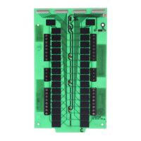
Figure 1 NCM-W
NCM-w.cdr
Diagnostic
LEDs
Network
Connection
Ports
(NUP)
Not used
Channel
A & B
Connections
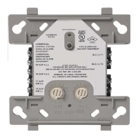
NCM-f.cdr
Figure 2 NCM-F
Diagnostic
LEDs
Network
Connection
Ports
(NUP)
Channel
A & B
Connections
Not used
12 Clintonville Road
Northford, CT 06472-1653 USA
www.notifier.com
NCM Installation Document
Network Communications Module NCM-W, NCM-F
PN 51533:A1 03/27/03 ECN 03-171