NCM Installation PN 51533:A1 03/27/03 3
2.2 Interconnecting the NCM-F
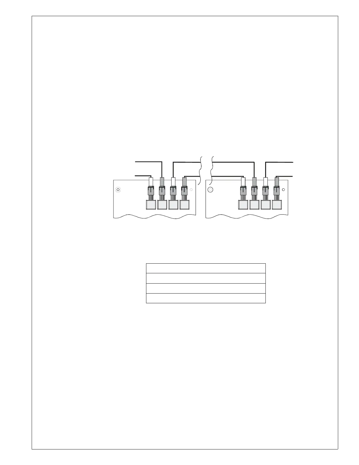
When connecting consecutive nodes/repeaters, note that fiber cable must exit one board on transmit
(TX) and enter the next node/repeater on receive (RX). Also, note that the fiber-optic pair (RX, TX)
from port A of one Node/Repeater may be connected to either Port A or Port B of another node/repeater
(refer to Figure 5). An NCM-F may be connected to any of the following devices:
• MIB-F
• MIB-WF
• NAM-232F
• Another NCM-F
• Network connection for NCS-F
•RPT-F
•RPT-WF
For information regarding these devices, refer to the NAM-232 and Repeater manuals listed in
Table 4 “Supplemental Documentation”.
Note: See the
NOTI•FIRE•NET™
Manual (Network Version 4.0 and Higher) for maximum fiber-
optic cable attenuation.
Figure 5 NCM-F Connection
Table 2 NOTI•FIRE•NET™ Connections: NCM-F
2.3 Mixing Wire & Fiber on One Network
In some networks, it may be necessary to mix twisted-pair wire and fiber-optic cable. There are two
solutions for this situation.
1. In any network, an RPT-WF may be used as an interface between wire and fiber.
2. In a network that uses an AFP1010 or AM2020, a MIB-WF may also be used as the interface
between wire and fiber.
See 1.2 “The Network Communications Module for Fiber (NCM-F)” for requirements and restrictions
on the use of fiber optic cable. See the
NOTI•FIRE•NET™
Manual (Network Version 4.0 and
Higher) for a discussion of all compatible configurations.
J200 CH A Transmit
J201 CH A Receive
J202 CH B Transmit
J203 CH B Receive
RxB TxATxB RxA
TXTX
J203
RXRX
J20 2
J20 1
J20 0
TXTX
J203
RXRX
J20 2
J20 1
J20 0
NCM-f-connex.cdr
RxB TxATxB RxA
Channel
B
Channel
A
Channel
A
Channel
B