2 NCM Installation PN 51533:A1 03/27/03
2 Installing the NCM
2.1 Interconnecting the NCM-W
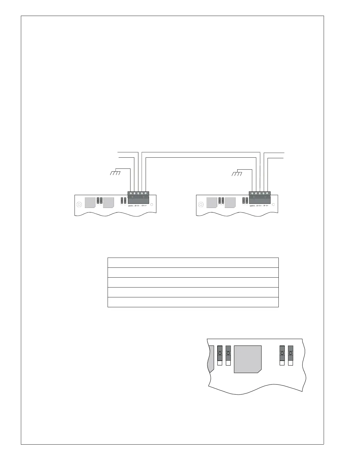
When wiring consecutive NCM-W boards, note that wiring may enter or exit at Port A or Port B as
shown in Figure 4. NCM-W port-to-port wiring is not polarity sensitive. The use of Port A or Port B is
arbitrary. An NCM-W may be connected to any of the following devices:
• MIB-W
• MIB-WF
• NAM-232W
• NCM-W (in another panel)
• NCS-W network connection
•RPT-W
•RPT-WF
For information regarding these devices, refer to the documentation listed in Table 4 “Supplemental
Documentation”.
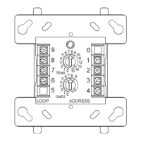
Figure 3 The NCM-W
Table 1 NOTI•FIRE•NET™ Connections: NCM-W
Switch Functions: Ground Fault Detection and Line Termination
The NCM-W provides two sets of switches to simplify
network setup; in Figure 4 all are in the “off” position.
• Enable ground fault detection by setting
switches “on”: SW103 for Channel A, and
SW101 for Channel B.
• Activate on-board end-of-line resistors by
setting switches “on”: SW100 for Channel A;
SW102 for Channel B.
Note: Correct configuration depends on your network
design; refer to the
NOTI•FIRE•NET™
Manual (Network Version 4.0 and Higher).
TB100-1 CH-A (+) Channel-A Driver/Receiver
TB100-2 CH-A (-) Channel-A Driver/Receiver
TB100-3 CH-B (+) Channel-B Driver/Receiver
TB100-4 CH-B (-) Channel-B Driver/Receiver
TB100-5 Earth Ground
B
A
B
A
EF B TERM B
SW101
SW10 2
SW103
ON OFF
EF A TERM A
SW10 0
ON OFF
EF B TERM B
SW101
SW10 2
SW103
ON OFF
EF A TERM A
SW10 0
ON OFF
ote: Wiring from the NCM-W that is installed outside the building:
Cannot exceed 1000m (3280 ft.).
Must be in conduit and is to be buried in a trench separate from any power lines.
Cannot cross any power lines.
From last node,
Port A
To next node,
Port B
NCM-w-connex.cdr
EF B TERM B
SW101
SW102
SW103
ON OFF
EF A TERM A
SW100
ON OFF
ncm-w-switches.cdr
Figure 4 NCM-W Switches