9
8
7
6
5
4
3
2
1
0
ADDRESS
0
0
1
2
3
4
5
6
7
8
9
TENS
ONES
7
8
6
5
4
3
2
1
9
10
11
12
13
14
15
N500-49-00 1 I56-1172-06
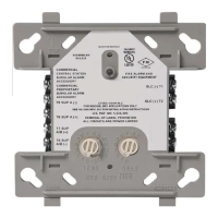
FZM-1 Interface Module
INSTALLATION AND MAINTENANCE INSTRUCTIONS
Before Installing
This information is included as a quick reference installa-
tion guide. Refer to the control panel installation manual
for detailed system information. If the modules will be
installed in an existing operational system, inform the
operator and local authority that the system will be tempo-
rarily out of service. Disconnect power to the control panel
before installing the modules.
NOTICE: This manual should be left with the owner/user
of this equipment.
General Description
The FZM-1 Interface Module is intended for use in intel-
ligent, two-wire systems, where the individual address of
each module is selected using the built-in rotary switches.
This module allows intelligent panels to interface and moni-
tor two-wire conventional smoke detectors. It transmits the
status (normal, open, or alarm) of one full zone of con-
ventional detectors back to the control panel. All two-wire
detectors being monitored must be UL compatible with this
module. The FZM-1 has a panel controlled LED indicator
and can be used to replace an MMX-2 module in existing
systems.
Compatibility Requirements
To ensure proper operation, this module shall be connected
to a compatible Notifier system control panel only (list
available from Notifier).
Mounting
The FZM-1 mounts directly to 4 square electrical boxes (see
Figure 2A). The box must have a minimum depth of 2
1
/8
.
Surface mounted electrical boxes (SMB500) are available
from Notifier
Wiring
NOTE: All wiring must conform to applicable local codes,
ordinances, and regulations. This module is intend-
ed for power-limited wiring only.
Figure 1. Removing
Rotary Switch Stop:
Figure 2A. Module mounting:
A78-2611-12
Figure 2B:
A78-2610-10
Specifications
Normal Operating Voltage: 15 to 32 VDC
Maximum Current Draw: 5.1 mA (LED on)
Average Operating Current: 270µA (LED flashing)
EOL Resistance: 3.9K Ohms
Maximum IDC wiring resistance: 25 Ohms
External Supply Voltage (between Terminals T3 and T4)
DC Voltage: 18-28 volts power limited (19 to 28VDC when used with MTL isolator model MTL3043 in
intrinsically safe applications)
Ripple Voltage: 0.1 Volts RMS maximum
Current: 90mA per module
Temperature Range: 32˚F to 120˚F (0˚C to 49˚C)
Humidity: 10% to 93% Noncondensing
Dimensions: 4
1
/2 H x 4 W x 1
1
/4 D (Mounts to a 4 square by 2
1
/8 deep box.)
Accessories: SMB500 Electrical Box
1. Install module wiring in accordance with the job draw-
ings and appropriate wiring diagrams.
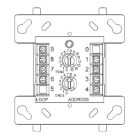
2. Set the address on the module per job drawings.
Note: Some panels support extended addressing. In
order to set the module above address 99 on compatible
systems, carefully remove the stop on the upper rotary
switch with thumb in the direction shown in Figure 1.
3. Secure module to electrical box (supplied by installer),
as shown in Figure 2A.
A78-2318-07
9
8
7
6
5
4
3
2
1
0
0
1
2
3
4
5
6
7
8
9
TENS
ONES
ADDRESS
LOOP
0
7
8
6
5
4
3
2
1
9
10
11
12
13
14
15
9
8
7
6
5
4
3
2
1
0
ADDRES
S
0
0
1
2
3
4
5
6
7
8
9
TENS
ONES
7
8
6
5
4
3
2
1
9
10
11
12
13
14
15
12 Clintonville Rd
Northford, CT 06472-1653
(203) 484-7161
www.PDF-Zoo.com