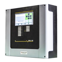
UDS-4 Installation and user manual PAGE - 37
UDS-4_manu M--203.1-UDS4N-ENG Rev A.1 NOTIFIER ITALIA
Automatic electrical control device is switch-off and delay management with
integrated power supply equipment
Compulsory, optional and accessory functions according to applied standards EN 54-4 - EN 12094-1
Notifier Italia Srl - Via Grandi 22 - 20093 San Donato Milanese ( Milan)
Compulsory functions (UNI EN 12094-1 4.3)
1) Reception and processing of incoming drive signal from s.r.a.i:
for each zone, it has two inputs to decree the activated condition (both must be active) and a loop input
for its connection with analogue control panels (d.e.c. is also an addressable device).
2) Transmission of the extinguishing signal:
for each zone has an output to control the actuator for switching off.
3) Activation of alarm devices:
for each zone has an output for activating the alarm devices (siren or optical acoustic device).
4) Indication of any ongoing condition:
For each zone, the current condition is shown by means of light signals and written indications in the
alphanumeric display.
5) Transmission of incorrect component status:
a common output signals the presence of faults.
6) Transmission of release condition information:
a common output signals the presence of the release condition.
7) Activated response delay condition max. 3 seconds
8) Activation of output response delay max. 1 second
Optional functions with requirements (EN 12094-1 4.3)
1) Delay of the extinction signal:
for each zone can be set from 0 to 60 seconds for automatic discharge in 5-second increments, and from
0 to 5 seconds for manual discharge in 1-second increments.
2) Reception of the signal representing the flow of the extinguishing agent:
each zone has a flow switch input.
3) Monitoring of component status:
each zone has a pressure switch input; the leakage agent is signalled by a separate warning light,
activation of the extinguishing system fault output and activation of the common fault presence output.
4) Signal reception from an emergency extension device:
each zone has a dedicated input; its activation is indicated by a separate beacon per zone and a common
output.
5) Reception of signals from accessory devices for switching to manual-only mode:
each zone has a dedicated input; its activation is indicated by a separate beacon per zone and a common
output.
6) Drive signal transmission to equipment within the fire extinguishing system:
Each zone has a pre-alarm output for signalling the pre-activated condition (activated when only one of
the two drive inputs is active), and an output to pilot cylinder/directional valve signalling the activated
condition.
7) Signal transmission to equipment outside the extinguishing system:
Each zone has an output to signal that the shutdown cycle has been successfully completed.
8) Reception of the signal from the emergency stop device:
each zone has a dedicated input; its activation is indicated by a separate beacon per zone and a common
output.
9) Activation of the alarm device with different signals:
for each zone the output for the alarm device is activated in three different ways to signal the
extinguishing signal delay, the extension of the emergency, the release of the extinguishing agent.
 Loading...