2 HS-NCM Installation Document — P/N 54014:B2 04/25/2014
2 The Network Communications Module for Wire (HS-NCM-W)
• Supports twisted-pair wire medium.
• NFPA Style 4 (Class B) operation or NFPA Style 7
(Class A) operation.
• Transformer coupling provides electrical isolation
between nodes.
• Pluggable terminal wiring with strain relief.
• Pluggable service connector (feeds signal directly
through) in the event that power must be removed from
a node (HS-NBB).
• Data is regenerated at each node.
• Two network ports to allow simultaneous connection
of up to two fire alarm control panels and a
programming computer.
• Enables software and database upload/download over
High-Speed Noti•Fire•Net.
Communication Circuit Voltage and Current Rating/Protocol
TB4 (Ch A - Wire Only) 10 VDC, 25mA
TB5 (Ch B - Wire Only) 10 VDC, 25mA
J6 (NUP) 232 Protocol
J7 (NUP) 232 Protocol
J13 (USBA) Standard Protocol
J14 (USBB) Standard Protocol
Table 1 Voltage and Current Ratings for Communication Circuits
NOTE: For use with the NFS-640, NFS2-640, NFS-320, NFS-3030, NFS2-3030, DVC-EM, NCA-2, and
NCA, the HS-NCM must be connected via the NUP Ports!
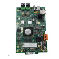
Ground Fault
Detection
Switches
S1=CH. A
S2=CH. B
Figure 1 HS-NCM-W
HS-NCMwire.wmf
NUP
Ports
Channel B
Connection
Channel A
Connection
USB
Connections
External
Power
Connection