Simple Set Reader and Keyfobs
The simple set reader can be installed in a range of
intruder system to allow ease of setting and unsetting the
system using a keyfob. Each keyfob is unique and cannot
be used unless it is recongised by the reader, which
provides total security. A reader can learn to operate with
up to eight keyfobs. There can be more than one reader
installed in a system. These instructions cover how to
mounting and wire the reader, where necessary how to
engineer the panel and learn up to eight keyfob at a reader
and how to operate the system using a keyfob.
The products covered are:
SS/01 ADE Simple Set Reader with 2 keyfobs
SS/01/UB Unbranded Simple Set Reader with 2 Keyfobs
SS/F ADE keyfob
SS/F/UB Unbranded keyfob
Do’s
Before you begin installation do:
ÿ
check the Simple set reader can be connected to your
intruder system and ensure the panel software is
compatible, see wiring and programming
ÿ
ensure the Tamper wiring is connected to the reader
ÿ
mount each reader away from metal surfaces and large
metal objects
ÿ
test the operation of the reader(s) using the keyfobs
ÿ
when using a keyfob, always hold the keyfob
perpendicular to the surface of the reader to achieve
maximum range, see photo above.
Technical Data
Mounting the reader
Wiring and programming
The simple set reader can be connected to an
ADE G3 or Accenta range of intruder panels.
The wiring diagrams here show connection
details, minimum panel software requirements
and programming procedures. It may be
possible to connect the reader to other intruder
system, for further information call Technical
Support for help.
ÿ
If you are installing the reader to an
existing system then you will need to
power down the system, note a tamper
alarm will occur.
ÿ
Once you have connected the reader to
your intruder panel you will need to
power up the system. On powering up, the
system will go into alarm. At a keypad
enter the user code and reset the system.
The Power and Day indicator should now
be lit at all keypads and also at the
readers.
ÿ
If the system requires programming to
accept a keyswitch input, then follow the
how to program instructions accompanying
the appropriate wiring details.
ÿ
You can now set and unset the system
using the keyfobs supplied with the reader,
see operating instructions.
ÿ
You must now test the system to check the
reader provides zone, tamper and attack
indications.
NOTE: If you have addition keyfobs or
have acquired new keyfobs to replace
lost ones, then you will need to learn the
keyfobs, see how to learn instructions.
draft
P2
RELAY
TAMP
SOUND
+13V
0V
COMMS
JUMPER
WD1
TAMP
Base
Cover assembly
Tamper spring
locating collar
6- Thinned
sections
for cable entry
Cover fixing
screw
Cable
entry
point
Mounting points
Tamper breakout
If required cut-out the appropriate thinned section on the base.
Route the external cable through the base and fix the base using the two mounting points.
Connect the external cable to the terminal block on the cover assembly, see also wiring diagrams.
Clip the cover assembly to the base and ensure the tamper spring locates into the collar
on the base. Secure the to the using thecover assembly base cover fixing screw.
Tamper Spring
Tamper
Spring
Base
Cover
assembly
J5
0V
TAMP
+13V
COMMS
SOUND
1A
RKP FUSE
F2
Panel
Board
Simple Set Reader
Board
COMMS
12V
SOUND
LD R
Board
SOUND
TAMP
COMMS
13V
0V
Keypad
Board
GND
OPTI-CAM Lighting
Controller
Where there is only one keypad and
it is part of the panel then connect
the TAMP back to the panel
How to connect the Simple Set Reader to a G3 intruder panel
with Version 2.1 (xx/xx/02) or above
SOUND
TAMP
COMMS
13V
0V
RELAY
Cable distance 100m maximum
Maximum of up to 4 Remote Keypad /
Reader /
OPTI-CAM Lighting Controller
combination allowed
Simple Set
J5
0V
TAM P
+13V
COMMS
SOUND
1A
RKP FUSE
F2
Panel
Board
Simple Set Reader
Board
COMMS
12V
SOUND
LD
R
Maximum of up to 4 Remote Keypad /
Reader /
OPTI-CAM Lighting Controller
combination allowed
Simple Set
Board
SOUND
TAMP
COMMS
13V
0V
Keypad
Board
GND
OPTI-CAM Lighting
Controller
How to connect the Simple Set Reader to a G3 range intruder panel
with Software versions 1.2 (26/11/01), 1.1 (12/09/01), 1.0 (08/06/01)
J2
Zone 8
SOUND
TAMP
COMMS
13V
0V
RELAY
Zone configured to accept
a Keyswitch input
Reset
Engineer Progam Mode
Prog
9 9 9 9 5 8
Zone
configuraion
Zone 8#
5
Keyswitch
Input Zone
Reset
Reset
# Enter appropriate zone number if it is not zone 8
How to program Zone 8 for keyswitch input
Cable distance 100m maximum
Where there is only one keypad and
it is part of the panel then connect
the TAMP back to the panel
Press
Simple Set Reader
Board
SOUND
TAMP
COMMS
13V
0V
RELAY
J5
0V
+13V
COMMS
SOUND
1A
RKP FUSE
F2
Panel
Board
SOUND
TAMP
COMMS
13V
0V
Keypad
Board
If the keypad is part of the
panel then connect the TAMP
back to the panel
How to connect the Reader to an Accenta 8 Panel
TAMP
PTS
PTS configured to
accept a Keyswitch input
Maximum of up to 4 Remote Keypad /
Simple Set Reader combination allowed
Reset
Engineer Progam Mode
Prog
9 9 9 9 6 5
Flag
Configuration
Keyswitch
input
How to program PTS as a remote keyswitch input
Cable distance 100m maximum
Press
Power - 13.8V dc from panel +/- 5%
maximum 75mA
Minimum range 20mm from centre of depression
keyfobs 8 maximum per reader
Dimensions 58.5 x 18.5mm 118 x 84 x 22mm
Weight 4g 114g
Temperature 0 to +40 C
Colour Dark Grey Polycarb. White ABS
Mounting - Screws
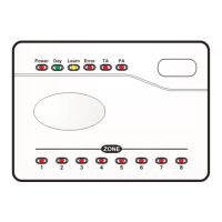
Indications - Day - (green)
Learn - (amber)
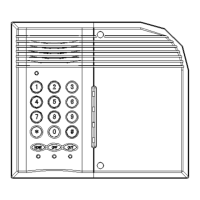
Keyfob Reader
SS/F & SS/F/UB SS/01 & SS/01/UB
º
Power, Zone, Error - (red)
TA, and PA - (red)
Power Day ErrorLearn PATA
12345 768
ZONE
22mm
118mm
84mm
Keyfob
18.5mm
58.5mm
Reader