Wiring the Outputs
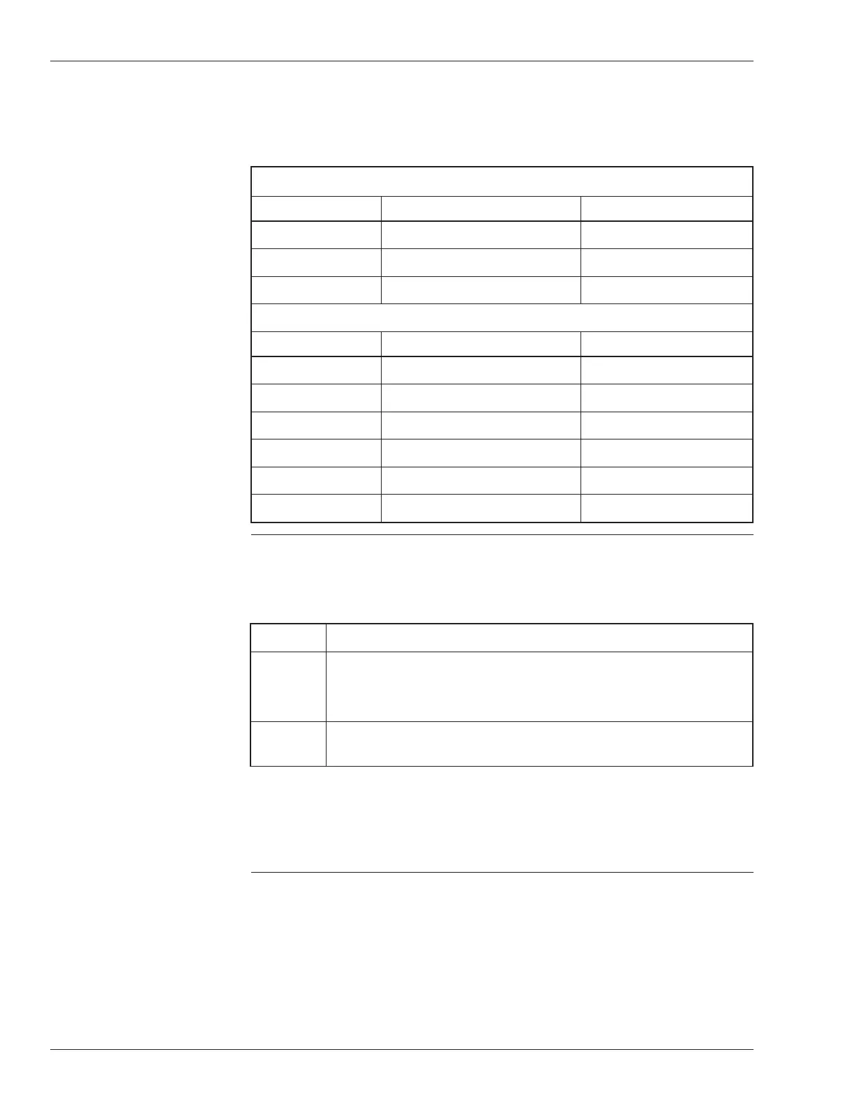
Table 1 outlines the HPC and HPC Plus analog and digital outputs.
Table 1. HPC and HPC Plus Digital and Analog Outputs
ANALOG OUTPUTS HPC PLUS HPC
Terminal 11 (D) Damper
Terminal 12 (E) Not Active
Terminal 13 (F) Used for General Fault Input
DIGITAL OUTPUTS HPC PLUS HPC
Terminal 21 (A) Fan Fan
Terminal 22 (B) Compressor Stage 2
Terminal 23 (C) Auxiliary Heat
Terminal 24 (D) Not Active
Terminal 25 (E) Reversing Valve Heating
Terminal 26 (F) Compressor Stage 1 Cooling
Damper Analog Output (HPC Plus Only)
The HPC Plus damper analog output terminals are listed under the label “Analog
Outputs” immediately to the right of the input connections (Figure 2).
Step Procedure
1 Connect the damper actuator’s control signal (+) to the Heat
Pump Controller Plus at Terminal 11 (D).
§
This isa0to10-Volt, 1 mA maximum connection.
2 Connect the damper actuator’s common or ground connection to
Terminal 14 (GND) of the HPC Plus.
Terminals 13 (F) and 14 (GND) are used for making a connection from a general
fault input (refer to the “Wiring the HPC or HPC Plus, Inputs, General Fault
Input [HPC Plus Only]” section of these instructions). Terminal 12 (E) is not
active.
6 DOC. #569062000 2/20/01
HPC/HPC Plus Installation Instructions