408A Manual
clock, the distortion may be unacceptable. There-
fore, the output is limited to approximately 40% of
the system clock and steep output filters are pro-
vided on board: in this case 7th-order elliptical low
pass filters.
5.6 If you are using an external clock and a Kp
which give a clock substantially lower than the
281.47MHz default internal clock, you may need to
filter the Sine and Cosine Outputs to obtain accept-
able distortion for your application. For best perfor-
mance, set the corner frequency at 40% or less of
your external clock frequency times Kp. The lower
your filter as a percentage of your clock frequency,
the lower the distortion.
NOTE:
Since filtering occurs before the signal is level
shifted to ACMOS/TTL, the ACMOS/TTL output
may be erratic or distorted when using low clock
frequencies. If you require an ACMOS/TTL level
signal when using low clock frequencies, it is
recommended that you use an external comparator/
level shifter connected to the output of your external
filter. Contact Novatech Instruments if you require
application assistance.
5.7 For example, if you are using a 10MHz external
clock, with the default reference multiplier (Kp) of
10, then the internal clock is 100MHz. An optimal
filter for this frequency would then be approxi-
mately 40MHz (40% of 100MHz).
5.8 In amplitude modulation (the “Z” command),
the modulation frequency is derived from the micro-
controller clock and is asynchronous to the carrier.
The modulation signal is unfiltered and is a stepwise
approximation to a sine wave.
6.1 Install the 408A as directed in the Serial Opera-
ti
on part of Section 3. Connect your host controller
and operate the 408A per Section 4. The test limits
assume a stable environment of 18-28
o
C.
6.2 The performance test detailed below verifies
each functional block on the 408A.
NOVATECH INSTRUMENTS
Allow the 408A to warm up for at least 15 minutes
before performing any measurements. For best
results, the 408A should be verified in its installed
environment.
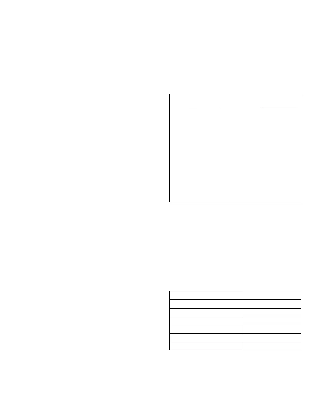
6.3 See Table 8 for a list of recommended test
equipment to perform the following measurements.
6.4
Verify Frequency Accuracy.
To verify the fre-
quency of the 408A, set the output sequentially to
each value in Table 9. Connect the recommended
frequency counter set to 50Ω termination and 1Hz
resolution. Verify the limits show in Table 9. Test
Sine (Q) Out, Cosine (I) Out and ACMOS Out to
verify functionality of all outputs. If you do not use
an external reference for the frequency counter, be
sure to add the error of your counter to the tolerance.
(LSD =
east
ignificant
igit on counter).
6.5
Sine (Q) Out Amplitude Verification.
Set the
frequency of the 408A to 100kHz. Connect the
408A to the DMM through a 50Ω feedthrough ter-
Table 8: Recommended Test Equipment
Oscilloscope 300MHz, 50
Ω
Tektronix
TDS3032
RF Probe 100kHz-
100MHz
Tektronix P6420
or HP34301A
DMM ACrms, dB HP34401A
50
Ω
Termination 50
Ω
,
1% Tektronix
011-0049-01
Frequency
Counter
120MHz HP53132A
Counter Time
Base
<
0.1ppm Novatech
Instruments
Model 2960AR
Table 9: Frequency Test Points
100 kHz
0.1Hz
1 LSD
1 MHz
1Hz
1 LSD
10 MHz
10Hz
1 LSD
30 MHz
30Hz
LSD
50 MHz
50Hz
1 LSD
99 MHz
99Hz
1 LSD
 Loading...