Do you have a question about the Novusun CNC NVEMV2.1 and is the answer not in the manual?
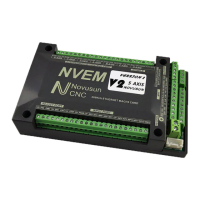
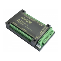
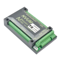
Introduces Novusun CNC and its expertise in motion control systems, highlighting the NVEMV2.1.
Details the NVEMV2.1's Ethernet support, photoelectric isolated I/O, and analog output capabilities.
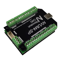
Describes the NVEMV2.1's sealed shell structure, mounting holes, and overall dimensions.
Explains common abbreviations used in the NVEM manual, such as FRO, SRO, SRJ, etc.
Provides critical warnings regarding environmental conditions, wiring, operation, and high voltage.
Details the power supply structure, common GND points, and isolation for the NVEM device.
Defines the pinout for the 6-axis stepper driver control output, including COM+, CP, and DIR signals.
Explains the spindle control output interface, including VSO for speed and INDEX for feedback.
Describes the internal structure and connection method for the common IO output ports.
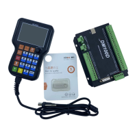
Details the MPG port terminals, their definitions, and the relationship between system and MPG wiring.
Specifies the main power supply input voltage (12-32VDC) and minimum current requirements.
Explains connections for ESTOP, limit switches, and tool setting inputs with optical isolation.
Guides on using the interface to modify FRO, SRO, and SJR parameters with switches and encoders.
Describes the Ethernet port for Mach3 communication, covering router and network cable modes.
Provides step-by-step instructions for installing the MACH3 software.
Explains how to register MACH3 by copying the Mach1Lic.dat file.
Details the process of copying the NVEM.dll file to the Mach3 plugins folder.
Guides on launching the mach3mill software and selecting the appropriate plugin.
Verifies that the NVEM plugin is correctly installed and active within Mach3.
Configures motor movement parameters like steps per, velocity, and acceleration for each axis.
Configures input and output signals for hardware interfaces like Ports & Pins and Motor Outputs.
Details the configuration steps for selecting and using the MPG controller within Mach3.
Guides on setting the machine's original position switch and homing configuration.
Explains how to move the tool tip to the workpiece zero point and clear coordinates.
Instructs on loading a G-code file and initiating the machine's operation via cycle start.
| Model | NVEMV2.1 |
|---|---|
| Input Voltage | 24V DC |
| Communication Interface | Ethernet |
| Software Compatibility | Mach3 |
| Pulse Frequency | 200KHz |
| Type | CNC Controller |
| Control Axis | 6 |
| Protection Features | Short circuit protection |